
Method and apparatus for the dynamic balancing of a rotating structure

a rotating structure and dynamic balancing technology, applied in adaptive control, computer control, instruments, etc., can solve the problems of inaccuracy of machined workpiece features, general presence of unsatisfactory vibrations, and out-of-balance conditions, and achieve the effect of safe use, rapid and reliable operation

Inactive Publication Date: 2005-04-12
MARPOSS SPA
View PDF15 Cites 9 Cited by
  • Summary
  • Abstract
  • Description
  • Claims
  • Application Information

AI Technical Summary

Benefits of technology

An object of the present invention is to provide a balancing method and an apparatus for the dynamic balancing of rotating systems, more specifically elongate structures including tools as grinding wheels, that enable to eliminate or reduce to a minimum the unwanted vibrations in a way that is rapid, safe and substantially does not depend on the structural features of the rotating system. This and other objects are achieved by a method according to claim 1, and by an apparatus according to claim 9. One of the advantages that a method according to the invention and, consequently, an associated apparatus provide is the application simplicity, that contributes to provide flexibility of use to rotating systems with tools of various shapes and arrangements.

Problems solved by technology

Undesired vibrations are generally present in a grinding machine, and generated by out-of-balance conditions of the grinding wheel due to various possible reasons depending on the grinding wheel itself, like shape and / or constitution defects (inhomogeneity of the materials, concentricity errors between the external abrading surface and the internal centering hole, etc.), inaccurate assembling to the rotating spindle (hence causing the wheel center of gravity to be spaced apart from the axis of rotation), and, in general, deteriorations due to wear and / or splinter occurring during the machining of the workpieces.
These vibrations may cause inaccuracies in the features of the machined workpieces—more specifically roundness errors like ovality and / or lobing—and introduce loads and stresses that may damage the machine tool.
Automatic balancings using deterministic criteria—i.e. balancing procedures including the performing of test cycles allowing to calculate the arrangement (for example the angular arrangement) of the masses that is able to balance the system—are more difficult and expensive to apply to rotors of machine tools, as it is required to continuously check the arrangement (for example the angular arrangement) of the movable masses in the device.
However, should the longitudinal layout dimensions of the grinding wheel be greater than, or even comparable with, its diametral dimensions (as in the case of grinding wheels of centerless grinding machines), or should the machine tool have two grinding wheels coupled to the same shaft, at longitudinally spaced out positions, a single balancing device that operates, in substance, along a transversal plane is not sufficient for achieving the appropriate balancing.
In fact, besides the so-called “static” out-of-balance at a specific area, it is not possible to disregard the dynamic couple balancing, caused by the fact that the axis of rotation that does not coincide, in general, with the axis of inertia of the rotating system.
In general terms the apparatus and the method described in the German patent application do not achieve satisfying results.
For this reason the apparatus and the method according to patent application DE-A-2345664 provide acceptable results only if applied to structures with very particular features but, in general terms, do not enable to overcome the problem of the correct dynamic balancing of rotating systems.

Method used


Image

  • Method and apparatus for the dynamic balancing of a rotating structure
  • Method and apparatus for the dynamic balancing of a rotating structure
  • Method and apparatus for the dynamic balancing of a rotating structure

Examples


Embodiment Construction

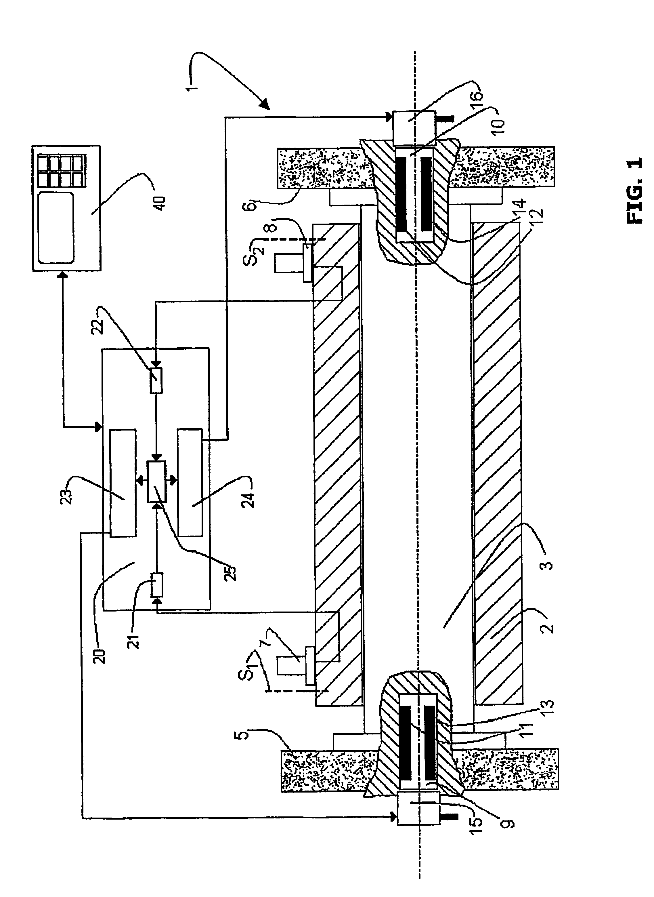
FIG. 1 illustrates, in simplified and partial form, an elongate rotating structure 1 that defines a longitudinal axis and includes a shaft or spindle 3 and two grinding wheels 5 and 6, coupled to the ends of the shaft 3 and spaced out along the longitudinal axis.

A grinding machine support 2, for example the wheel-carrier, defines an axis of rotation and supports the rotating structure 1 in such a way that the longitudinal axis substantially coincides with the axis of rotation, and the spindle 3, that is driven in a known way not shown in the FIG. can rotate about said axis.

Two vibration-detecting sensors 7 and 8, for example of the piezoelectric type, are fixed to the stationary support 2 near transversal checking sections S1 and S2, near the ends of shaft 3.

Balancing devices 9 and 10 are housed, for example, in suitable recesses at the ends of the spindle 3 near the transversal sections S1 and S2 and each includes a pair of eccentric balancing masses—shown in simplified form and id...


PUM


Abstract

A method and an apparatus for balancing an elongate structure (1) rotating about an axis, like a spindle (3) carrying two grinding wheels (5, 6), wherein two vibration-detecting sensors (7, 8) and associated balancing devices (9, 10) with movable masses (11-14) are arranged at two checking sections (S1, S2) spaced out along the axis of rotation. Processing and control means (20) control the balancing devices on the basis of one or more signals (VC; VC1, VC2) achieved as combination(s) of the vibrations, in module, detected by both the sensors.

Description

TECHNICAL FIELDThe present invention relates to a method for the dynamic balancing of a rotatable structure rotating about a longitudinal axis, by means of an apparatus including two vibration-detecting sensors, two associated balancing devices, and processing and control means adapted for processing signals output from the two vibration-detecting sensors and for controlling the balancing devices, the method including the steps of arranging each vibration-detecting sensor and its associated balancing device near a checking section, the two checking sections being spaced out along the longitudinal axis, and controlling the operation of the balancing devices on the basis of the signals of the two vibration-detecting sensors. The invention also relates to an apparatus for implementing said method.BACKGROUND ARTThe problem of balancing grinding wheels of grinding machines is known from time. Undesired vibrations are generally present in a grinding machine, and generated by out-of-balanc...

Claims


Application Information

Patent Timeline
Patent Type & Authority Patents(United States)
IPC IPC(8): G01M1/36G01M1/00G01M1/02H02K15/16
CPCG01M1/36
Inventor MONTANARI, WILLIAMDANIELLI, FRANCO
Owner MARPOSS SPA
Learn More