
Method of manufacturing glued laminated wood

a manufacturing method and laminate technology, applied in the direction of manufacturing tools, paper/cardboard containers, veneer presses, etc., can solve the problems of affecting the quality of the resulting product, the failure of a part of the paired combined veneer sheet to receive direct hot pressing action from the hot press, and the inviting of board breakage, etc., to achieve the effect of strength and quality

Inactive Publication Date: 2005-04-12
MEINAN MASCH WORKS INC
View PDF7 Cites 18 Cited by
  • Summary
  • Abstract
  • Description
  • Claims
  • Application Information

AI Technical Summary

Benefits of technology

This approach ensures that all veneer sheets receive uniform heat and pressure, resulting in improved bonding strength and quality of the glued laminated wood, reducing the risk of breakage under bending forces and enhancing the overall structural integrity.

Problems solved by technology

As is apparent to those skilled in the art, if end joints in any two adjacent layers are located in alignment with each other across the thickness of the board, stress tends to be centered at such joints when the board is subjected to bending force, thereby inviting breakage of the board.
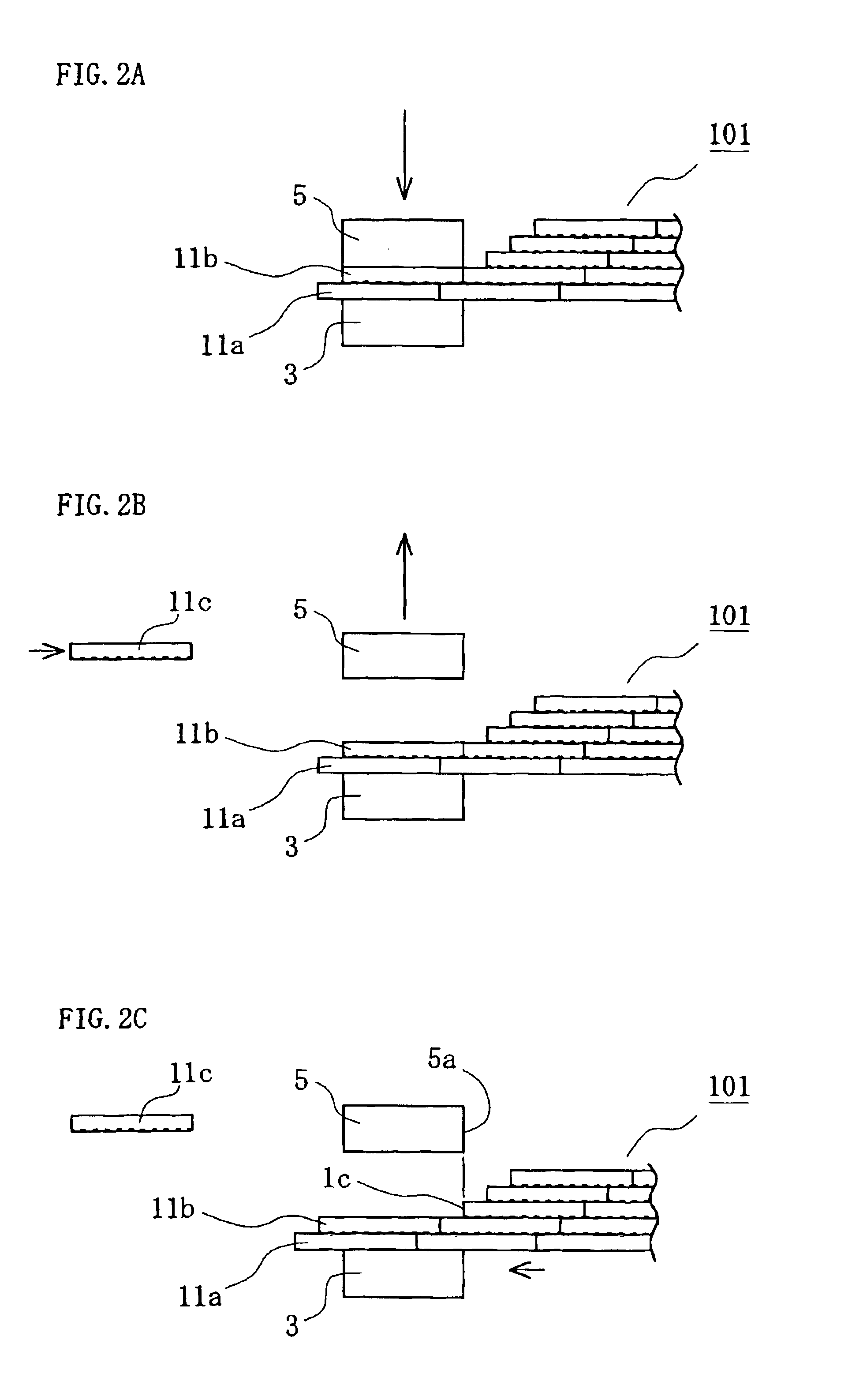
In hot pressing a pair of veneer sheets A, B or C in an offset or staggered arrangement as shown in FIG. 73 in the above apparatus, however, part of the paired combined veneer sheets fails to receive direct hot pressing action by the hot press.
As a result, the upstream end portions of veneer sheets will not be bonded with the desired strength, thus affecting the quality of the resulting product.

Method used


Image

  • Method of manufacturing glued laminated wood
  • Method of manufacturing glued laminated wood
  • Method of manufacturing glued laminated wood

Examples


fourth embodiment

the invention, which will be described in the following with reference to FIGS. 32 through 45, has been contemplated so as to avoid the above disadvantage.

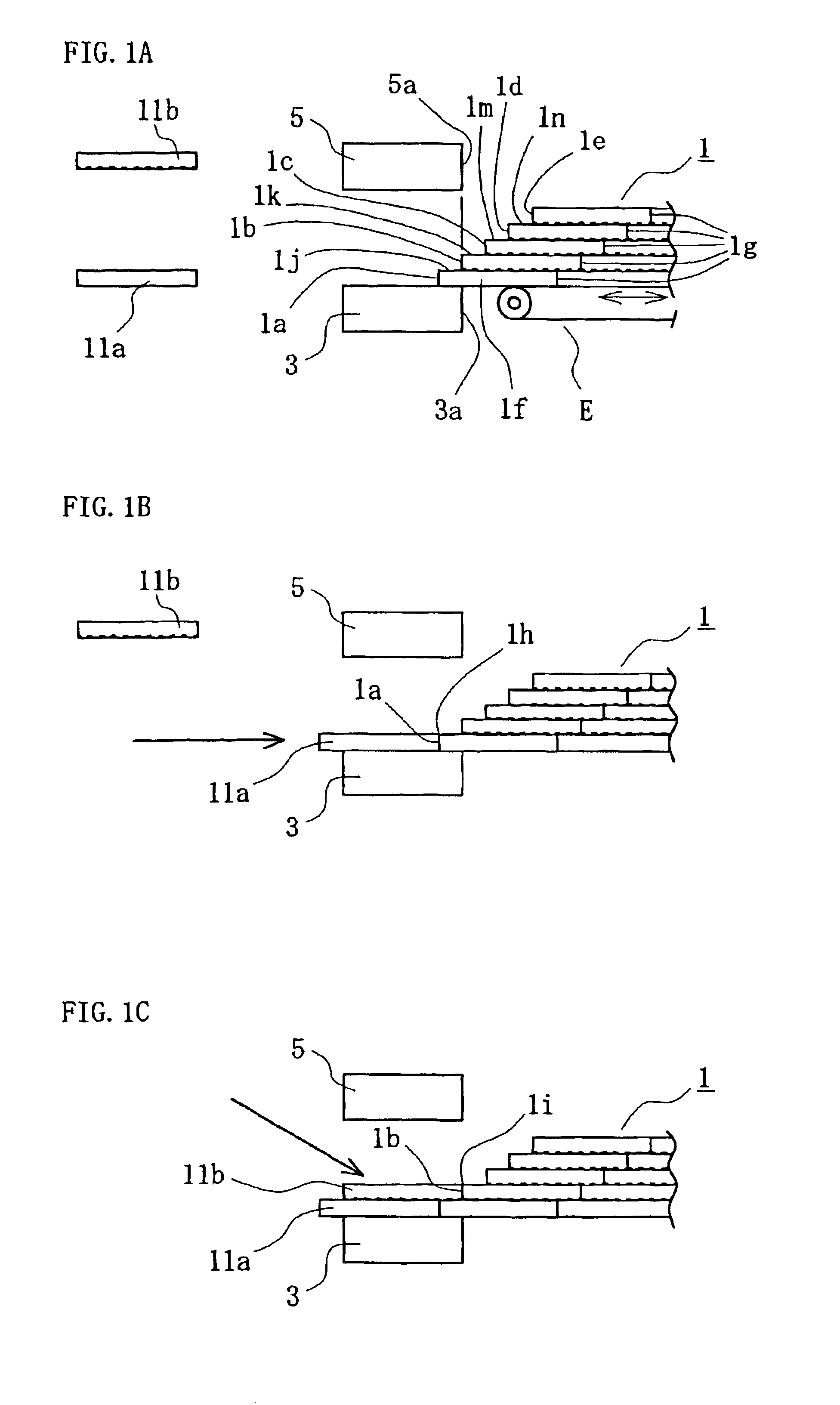
Referring to FIG. 32, there is shown an initial veneer stack assembly 6 of nine-layered configuration arranged in the same manner as the initial veneer stack assembly 2 of FIG. 5 for the second preferred embodiment. Though not shown, the veneer stack assembly 6 is supported on the reciprocally movable conveyer E.

Reference numerals 7 and 8 designate a pair of lower and upper heat plates movable toward and away from each other in the same manner as the heat plates 4 and 5 in the above second and third embodiments. The lower heat plate 7 is L-shaped as seen in its longitudinal cross-section, as shown in FIG. 32, having a veneer sheet receiving surface 7b adjacent to the right end face 7a and an elevated surface 7c adjacent to the opposite end. Between the surfaces 7b and 7c is formed a vertical stepped surface 7d. The receiving surfa...


PUM

PropertyMeasurementUnit
widthaaaaaaaaaa
lengthaaaaaaaaaa
lengthaaaaaaaaaa

Abstract

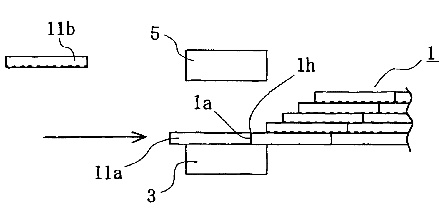
A method of manufacturing glued laminated wood such as laminated veneer lumber (LVL) is disclosed. The glued laminated wood is made of a number of wood sheets such as veneer sheets which are laminated together by a hot press with a thermosetting adhesive into a continuous length of multiple-layered board wherein the end joints of the wood sheets are disposed in a staggered array. There is provided an initial base material having an end which is shaped in the form of a flight of steps including a series of alternate horizontal surface having a lengthwise dimension smaller than the length of the wood sheet and a vertical surface having a height corresponding to the wood sheet thickness, and the glued laminated wood board is formed extending from the end of such initial base material. The hot press includes a pair of heat plates each having an effective pressing area capable of covering the entire surface of the wood sheet. In hot pressing a wood sheet having on one surface thereof coated with adhesive, a board of the glued laminated wood in progress is placed and maintained for a predetermined length of time at a position where the entire top surface of the wood sheet is kept to be pressed from the top by one of the plates while the entire lower surface of the wood sheet is supported from the bottom by the other plate.

Description

BACKGROUND OF THE INVENTION1. Field of the InventionThe present invention relates to a method of manufacturing glued laminated wood which is made of wood sheets such as veneer sheets provided by rotary peeling, slicing, or other wood material as obtained by sawing or otherwise prepared. More specifically, it relates to a method of laying such wood sheets and laminating them together successively by means of thermosetting adhesive thereby to produce the glued laminated wood in the form of a multiple-layered board or a billet with a desired thickness and length.2. Description of the Related ArtFor better understanding of the underlying background of the present invention, firstly reference is made to FIG. 73 which schematically shows a prior art apparatus for making laminated veneer lumber (LVL) wherein veneer sheets are laminated together the end joints thereof disposed in a staggered array and with the wood grain of each veneer sheet running primarily along the length of the resulti...

Claims


Application Information

Patent Timeline
Patent Type & Authority Patents(United States)
IPC IPC(8): B27D3/00B27D1/00B27M3/00B27D1/10
CPCB27D1/10B27D3/00B27M3/006Y10T156/1322Y10T156/1751Y10T156/10Y10T156/1075Y10T156/13
Inventor ABE, YUKIOISOBE, MAKOTOOKAMURA, ISSAKUODA, HIROSHIGEHAMAGUCHI, AKIHITOHONDA, NORIYUKI
Owner MEINAN MASCH WORKS INC
Learn More