
Vacuum pump

a vacuum pump and axial magnetic bearing technology, applied in the direction of bearings, shafts, dynamo-electric machines, etc., can solve the problem of not allowing a control of bearing forces, and achieve the effect of improving the axial magnetic bearing of the vacuum pump

Inactive Publication Date: 2005-04-12
LEYBOLD VAKUUM GMBH
View PDF21 Cites 27 Cited by
  • Summary
  • Abstract
  • Description
  • Claims
  • Application Information

AI Technical Summary

Benefits of technology

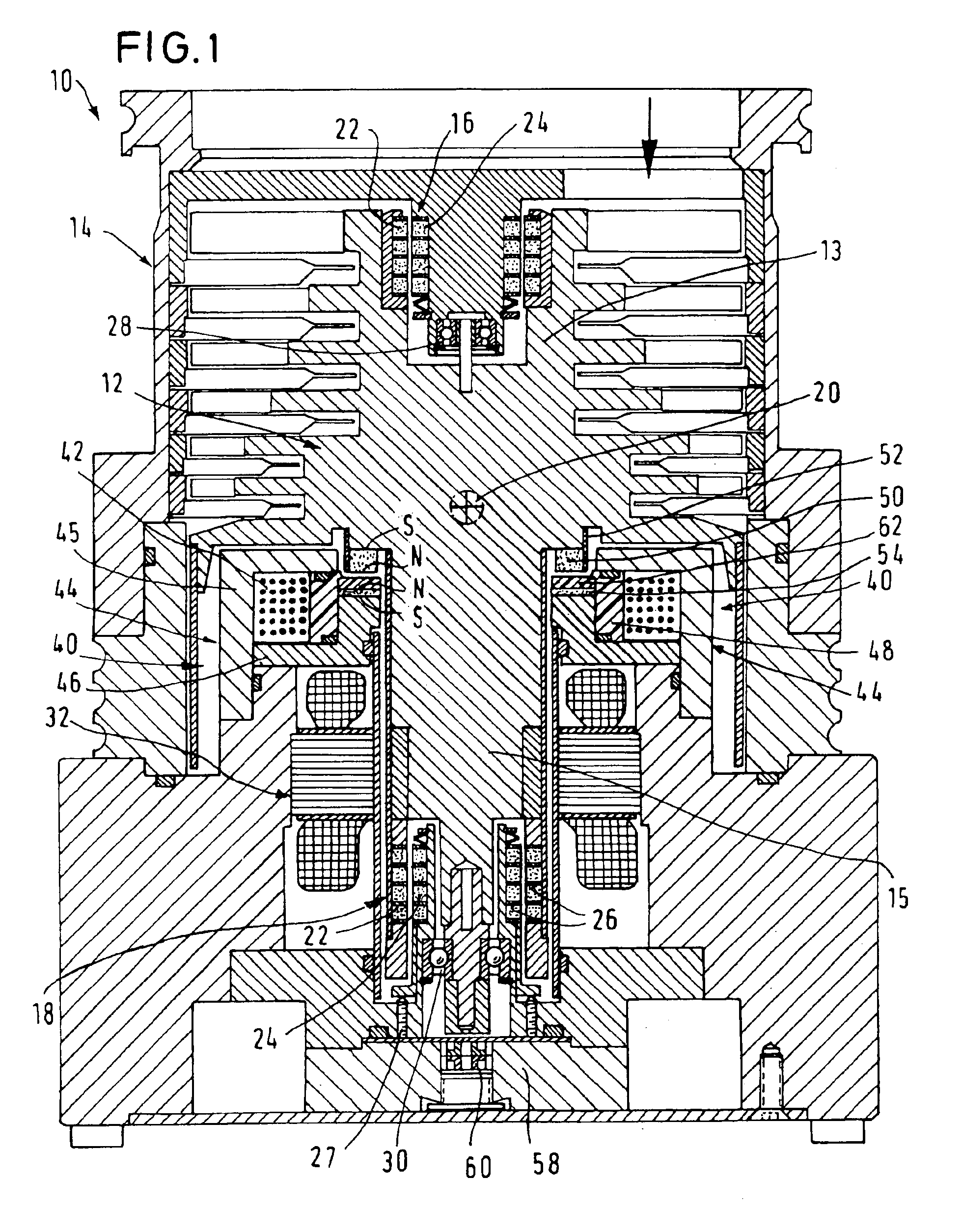
With the axial bearing of the vacuum pump according to the invention, the stator is provided with a permanently axially magnetized compensating magnet compensating the force effect of the magnetic field of the permanent magnet of the rotor upon the yoke iron. The compensating magnet is arranged so as to be polarized in opposite direction to the permanent magnet of the rotor so that the permanent magnet of the rotor and the compensating magnet repel each other. Separated by an air gap, the compensating magnet can be arranged directly opposite the permanent magnet of the rotor, but can also be arranged at another site of the extension of the yoke iron. The compensating magnet approximately compensates the axial forces of attraction between the permanent magnet of the rotor and the yoke iron of the stator. Thereby, an axial bias in the axial magnetic bearing is avoided. Therefore, the rotor can be held in a bias-free central position by means of the magnet coil. Because of the elimination of the axial bias, smaller magnet coils can be used for the safe control of the axial central position of the rotor. Due to the fact that the control forces of the magnet coil that have to be applied can be smaller, the heat development by the magnet coil is also considerably reduced.
According to a preferred embodiment, the stator comprises an eddy current damping disk of electrically conductive material that is axially arranged between the permanent magnet of the rotor and the yoke iron. The eddy current damping disk effects a dampening of radial movements of the rotor by the eddy currents induced in the damping disk in the case of radial rotor movements. Thus, an effective radial dampening is realized which can be provided as an alternative or in addition to the active dampening of tilting movements of the rotor.
Preferably, the axial bearing is arranged approximately radially with respect to the center of gravity of the rotor and between the two radial bearings each of which is arranged axially with respect to the center of gravity of the rotor. The center of gravity of the rotor is located between the two radial bearings, whereas the axial bearing is located approximately in the transverse plane of the center of gravity. With this arrangement, a high tilt stability of the rotor is realized. At the same time, the axial bearing is arranged such that the magnetic axial bearings can effect a high torque for generating a corresponding tilting moment of the rotor.
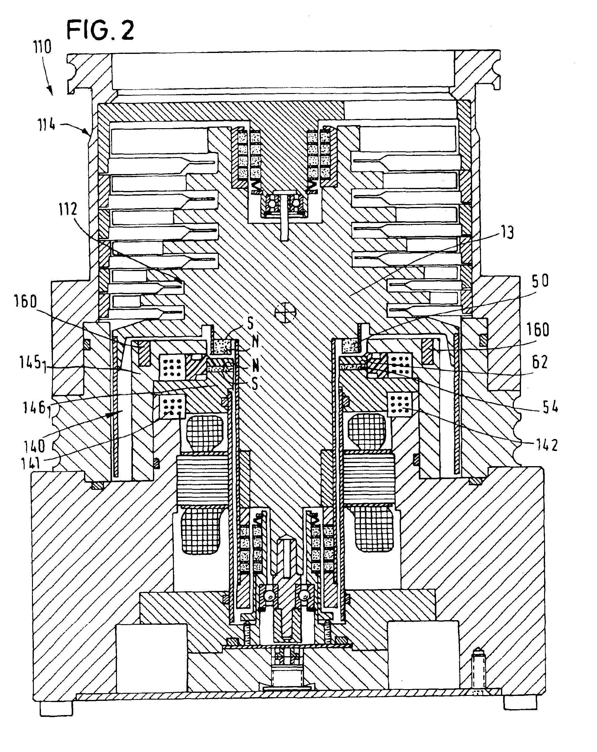
Preferably, the yoke iron, together with the compensating magnet, is inclined to the axial line and / or arranged so as to be radially offset with respect to the permanent magnet of the rotor. Thus, the air gap between the yoke iron and the compensating magnet, on the one hand, and the permanent magnet of the rotor, on the other hand, is inclined to the transverse plane and its surface is enlarged so that the use of larger magnets and, as a result, the realization of greater magnetic forces is made possible.
Preferably, one end of the yoke iron is arranged axially and the other end of the yoke iron is arranged radially with respect to the permanent magnet of the rotor. Because of the fact that the free yoke iron end is arranged radially outside or inside with respect to the permanent magnet of the rotor, a non-interlocked arrangement of the parts of the axial magnet bearing is realized. The complete rotor can be axially inserted into the stator from one side and be taken out of it, respectively. Thereby, a simple mounting of the rotor in the stator is facilitated.
When the permanent magnet of the rotor and the compensating magnet are arranged radially outside with respect to the magnet coil, the permanent magnet of the rotor and the compensating magnet can have a relatively large configuration so that great magnetic forces can be produced. Thereby, the axial bearing as well as the stabilization against tilting movements of the rotor are improved.

Problems solved by technology

Because of the possibility of avoiding tilting movements of the rotor by an appropriate control of the magnet coils of the axial bearing, it is possible to use exclusively permanent magnets for the radial bearing(s), which do not allow a control of the bearing forces.

Method used


Image

  • Vacuum pump
  • Vacuum pump
  • Vacuum pump

Examples


third embodiment

In a vacuum pump 210 illustrated in FIG. 4, the magnet coils 241-243 are arranged radially inward and the rotor ring magnet 250, the stator compensating magnet 254 and the damping disk 262 are arranged radially outward with respect to the magnet coils 241-243. Thereby, larger permanent magnets are made possible that produce a larger torque upon the rotor and thus a greater stabilizing effect. By the larger permanent magnets, the carrying power of the axial bearing is increased.

fourth embodiment

In a vacuum pump 310 illustrated in FIG. 5, the permanent magnet 350 of the rotor, the compensating magnet 354 of the stator and the damping disk 362 as well as the gap formed between the damping disk 362 and the permanent magnet 350 of the rotor are not arranged precisely in the transverse plane but inclined at an angle of approximately 15° thereto. The direction of magnetization of the magnets 350, 354 is also inclined by 15° with respect to the transverse plane. The magnetic forces transferred between the stator 314 and the rotor 312 are increased thereby, and they have both an axial and a smaller radial component. Thus, both the axial position of the rotor 312 in the stator 314 and the radial position of the rotor 312 in the stator 314 can be controlled by a suitable control of the magnet coils 141-143. Radial swerves and vibrations of the rotor can be reduced to a minimum thereby.

Because of the compensation of the forces of attraction between the permanent magnet of the rotor a...


PUM


Abstract

A rotor (12) is mounted in a stator (14) with radial magnetic bearings (16, 19) and with an axial magnetic bearing (40) in a contactless manner. The axial magnetic bearing (40) produces an axial magnetic field with a magnet coil (40) and a yoke iron (44) mounted on the stator (14). An axially magnetized permanent magnet (50) is provided on the rotor (12), located approxaimately axially opposite the yoke iron (44). A permanently axially magnetized compensating magnet (54) is provided on the stator (14) and arranged axially opposite the permanent magnet of the rotor (50) and polarized in the opposite direction, such that the permanent magnet (50) of the rotor and the compensating magnet (54) repel each other. In a center position, the rotor is bias-free by compensating the forces of attraction between the permanent magnet of the rotor and the yoke iron. As a result, the center position of the rotor can be adjusted with relatively small magnet coil flows. This results in small magnet coils, produces less heat and reduces the required power of the axial bearing.

Description

BACKGROUND OF THE DISCLOSUREThe invention relates to a vacuum pump with a stator on which a rotor with at least one radial magnetic bearing and an axial magnetic bearing is supported in a contactless manner.In vacuum pumps, magnetic bearings are frequently used for bearing the rotor. Magnetic bearings permit high rotational speeds of the rotor and are lubricant-free, whereby a pollution of the vacuum side of the pump by lubricant is excluded. From U.S. Pat. No. 5,166,566, a vacuum pump is known where the radial bearings are each formed by permanent magnet rings arranged so as to be slightly axially offset with respect to each other. Since the magnetic rings repelling each other also repel each other in an axial direction due to the offset arrangement, the rotor is biased in an axial direction. At an axial end of the rotor, a large lifting magnet is arranged which has an attracting effect upon a rotor disk. The lifting magnet is controlled in such a manner that it keeps the rotor in ...

Claims


Application Information

Patent Timeline
IPC IPC(8): F04D19/00F04D19/04F04D29/04F04D29/056F04D29/048F04D29/058F16C39/06
CPCF04D19/048F04D29/058F16C32/0478F16C32/047F16C2360/45F04D29/051
Inventor BEYER, CHRISTIANENGLANDER, HEINRICHHODAPP, JOSEF
Owner LEYBOLD VAKUUM GMBH
Learn More