
Ion-Ion plasma processing with bias modulation synchronized to time-modulated discharges

a technology of ion-ion plasma and bias modulation, which is applied in the field of plasma processing methods and systems, can solve the problems of difficult to maintain plasma without electrons, difficult to couple power into the plasma, and inability to generate useful electron-free ion-ion plasmas directly, etc., and achieves the effect of reducing the risk of charging up and complete control of ion bombardment energy

Inactive Publication Date: 2005-04-05
UNIVERSITY OF TEXAS AT DALLAS +1
View PDF29 Cites 20 Cited by
  • Summary
  • Abstract
  • Description
  • Claims
  • Application Information

AI Technical Summary

Benefits of technology

Finding a method to bring electrons to the bottom of high-aspect-ratio features could remove this charge imbalance and improve plasma-etch performance. This has been tried with some success. For example, Hashimoto et al., 35 Jpn. J. Appl. Phys., Part 1, 3363 (1996) described a method of bringing cool electrons in the afterglow to a processing surface from an argon plasma. The idea was to allow electrons to cool in the afterglow of a plasma so that the sheath potential and size decreases, the plasma expands closer to the wafer surface and thus better neutralizes the accumulated surface charge from the active glow. Of course, electrons do not etch the surface so etch rates suffer some.
Some plasma processing units have used “downstream” configurations, in which a plasma discharge is physically separated from the substrate being treated. By placing the substrate downstream from the plasma discharge, with a physical separation of e.g. several tens of centimeters, the gas flow can be given an “afterglow” like condition, i.e. can contain a significant population of negative ions. In such techniques the electron population can be very low at the point where the gas flow encounters the substrate. However, these techniques are different from the ion-ion plasma techniques used in the present application, in that the reduction in electron density is largely due to diffusion rather than attachment. This leads to reduced density of ions at the wafer surface as ions are lost to diffusion as well, which may be undesirable. By contrast, pulsed-plasma afterglow techniques can provide a much higher density of ionized species in proximity to the wafer surface.
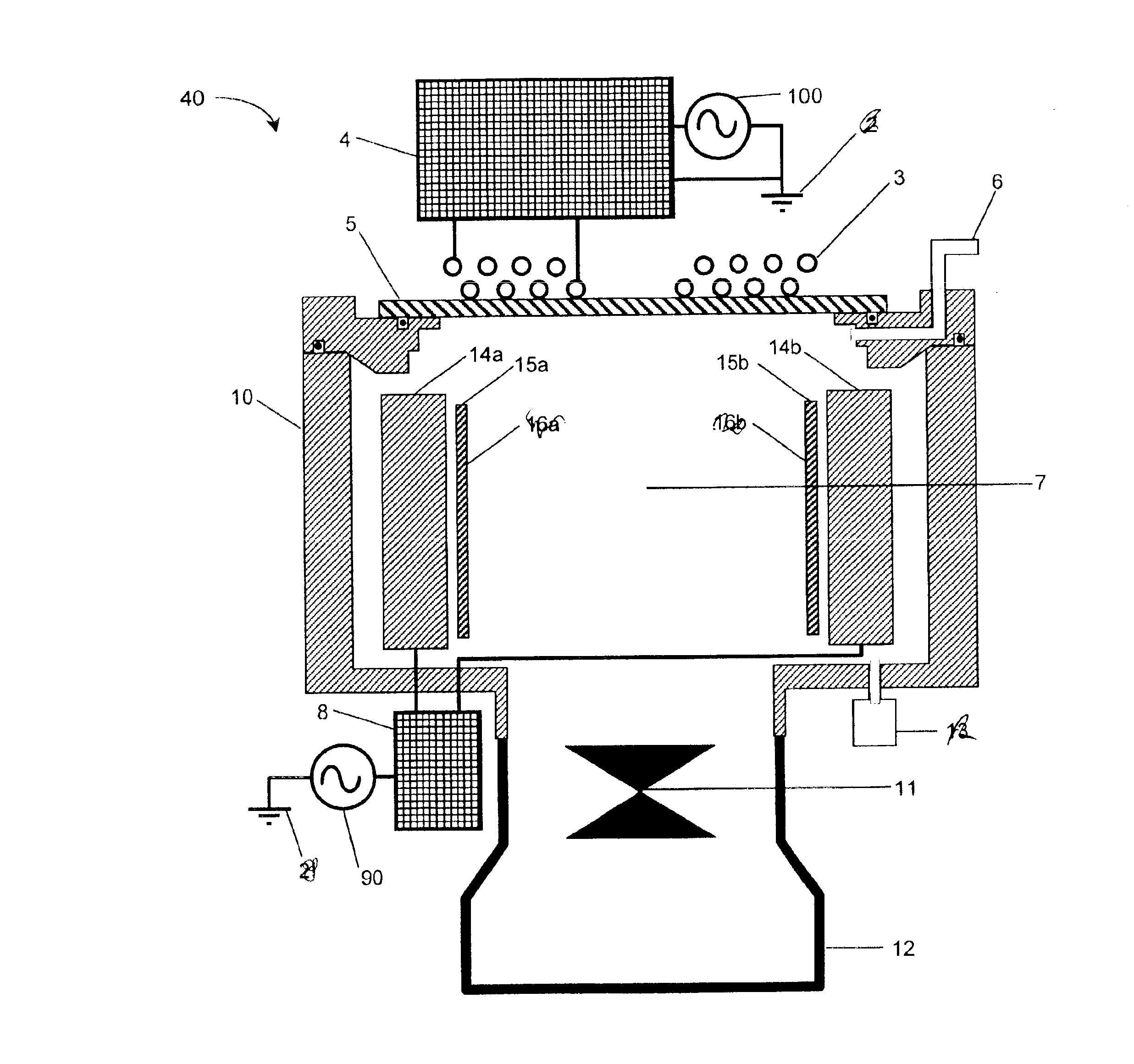
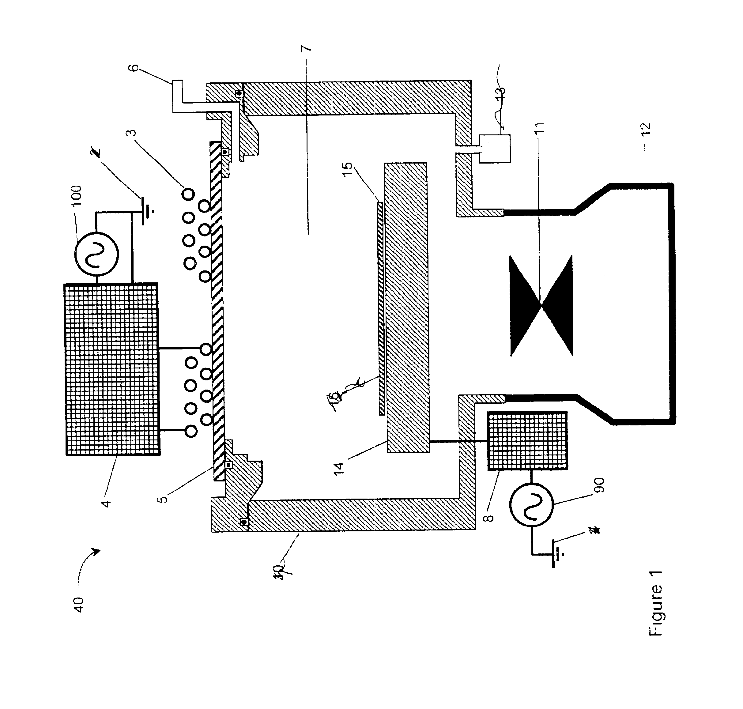
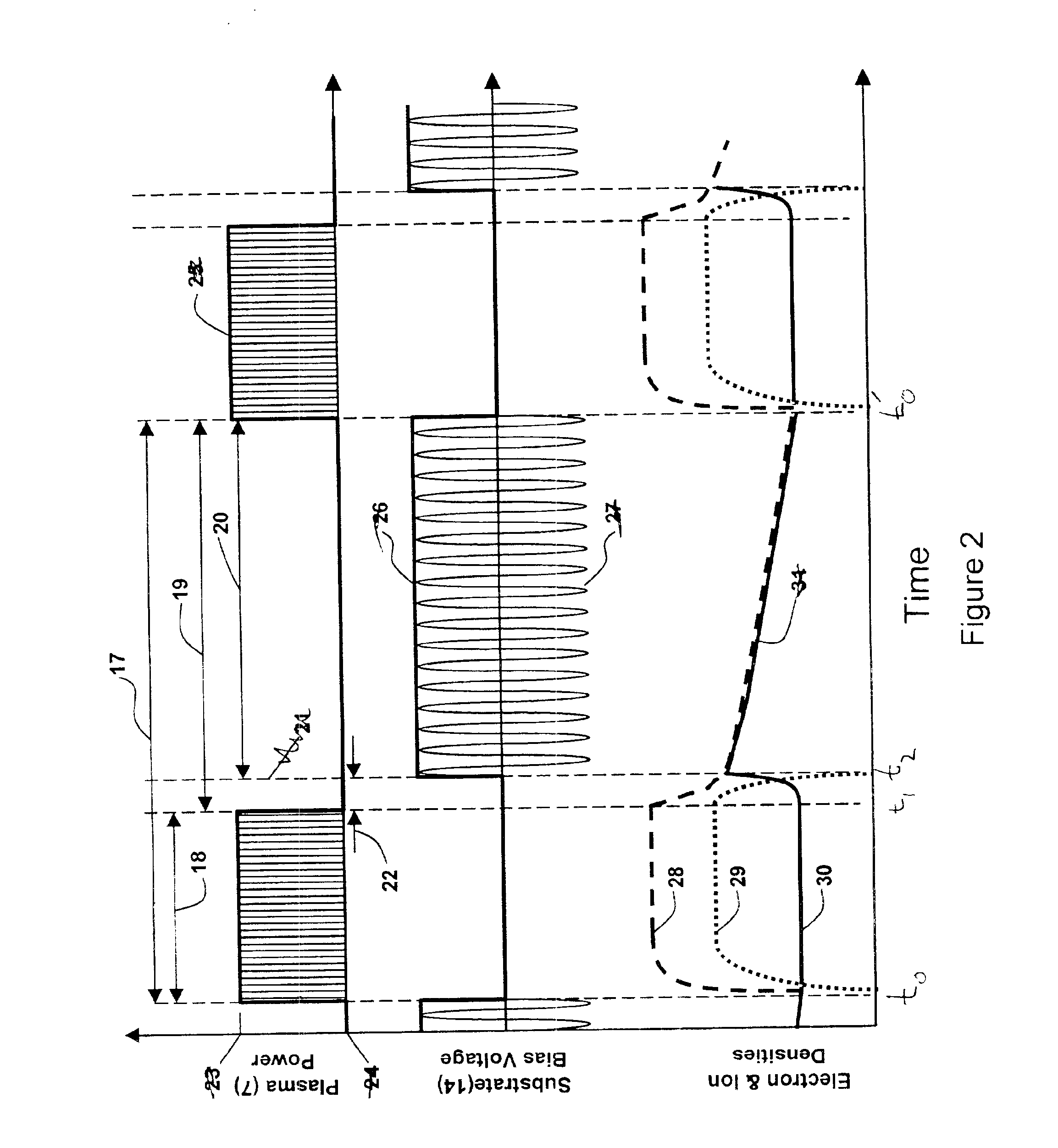
The disclosed ion-ion systems and methods can produce alternating bombardment of a processing substrate by positive and negative ions, such that the charges of the ions balance and the substrate never endures any significant charge buildup. Such methods, in various embodiments, can be used to process materials with high aspect ratio features without the deleterious “electron shading” effects common in present technology. It can allow the user to vary the surface chemistry in novel and beneficial fashions. It can also provide significantly better control over ion energies.
The disclosed innovations, in various embodiments, provide one or more of at least the following advantages:complete control over ion bombardment energy;reduced risk of charging up;maximal etch efficiency, especially in the fraction of available electron-free plasma time during which ion bombardment actually occurs;capability to combine positive-ion and negative-ion bombardment; andcapability to combine maximal etch rate with minimal electron impingement.

Problems solved by technology

If the electron population becomes very low, it will become more difficult to couple power into the plasma.
Thus, it is difficult to maintain plasma without electrons.
In practice, useful electron-free ion-ion plasmas cannot presently be generated directly, i.e. cannot be generated without use of an electron-ion plasma at some point.
The resulting charge separation is believed to modify the trajectories of subsequent ions, and to cause significant problems such as: lateral etching (notching), trenching, bowing, and dielectric breakdown.
It is difficult to quickly change the DC-bias once it has formed and consequently, the DC-bias on a wafer surface can often remain for extended periods after the plasma has been extinguished.
Of course, electrons do not etch the surface so etch rates suffer some.
His description is flawed, however in that it never describes a synchronization of the substrate bias pulsing to the high and low power cycles of the plasma power.
However, these techniques are different from the ion-ion plasma techniques used in the present application, in that the reduction in electron density is largely due to diffusion rather than attachment.
This leads to reduced density of ions at the wafer surface as ions are lost to diffusion as well, which may be undesirable.

Method used


Image

  • Ion-Ion plasma processing with bias modulation synchronized to time-modulated discharges
  • Ion-Ion plasma processing with bias modulation synchronized to time-modulated discharges
  • Ion-Ion plasma processing with bias modulation synchronized to time-modulated discharges

Examples


Embodiment Construction

The numerous innovative teachings of the present application will be described with particular reference to the presently preferred embodiment (by way of example, and not of limitation). The following description is intended to enable any person skilled in the art to make and use the invention. Any descriptions of specific applications are provided only as examples. Various modifications to the preferred embodiment will be readily apparent to those skilled in the art and the generic principles described herein may be applied to other embodiments and / or applications without departing from the scope of the invention.

Aspects of the present invention provide an improved plasma processing method that, in various embodiments, provide one or more of the following advantages: elimination of substrate charging during processing; improved control over ion energies; the capability to alternate positive-ion and negative-ion bombardment of a substrate; the capability to control surface chemistry...


PUM

PropertyMeasurementUnit
Fractionaaaaaaaaaa
Fractionaaaaaaaaaa
Poweraaaaaaaaaa

Abstract

A system for plasma processing using electron-free ion-ion plasmas, wherein the substrate bias waveform is synched to a pulsed RF drive. A delay is included between the end of an RF drive pulse and the start of a bias pulse, to allow the electron population to drop to approximately zero. By using a source gas mixture which has highly electronegative components, substrate bombardment with negative ions can be achieved.

Description

BACKGROUND AND SUMMARY OF THE INVENTIONThe present invention relates to plasma processing methods and systems, and particularly to processing with electron-free ion-ion plasmas in proximity to a microelectronic wafer surface.“Plasma” is a state of matter that includes a significant number of free charges (ions and / or electrons). Useful plasmas are often gaseous, but the presence of free charge causes plasmas to behave very differently from neutral gases.Plasma processing is one of the core technologies of the microelectronics industry. It is used for several functions, e.g. to deposit materials onto substrates, etch material from substrates, and to clean and / or chemically change a surface. Such plasmas are usually plasmas of the “glow discharge” type. (There are many other types of plasmas, ranging over a vast range of density and temperature, which are not relevant to such glow discharge plasmas.)The plasma is usually formed by applying electromagnetic power to a neutral gas near t...

Claims


Application Information

Patent Timeline
IPC IPC(8): H01J37/32H01L21/00
CPCH01J37/321H01L21/67069H01J37/32706H01J37/32422
Inventor KANAKASABAPATHY, SIVANANDA K.OVERZET, LAWRENCE J.
Owner UNIVERSITY OF TEXAS AT DALLAS
Learn More