
Recessed part forming instillation container

Inactive Publication Date: 2005-04-05
SANTEN PHARMA CO LTD
View PDF19 Cites 32 Cited by
  • Summary
  • Abstract
  • Description
  • Claims
  • Application Information

AI Technical Summary

Benefits of technology

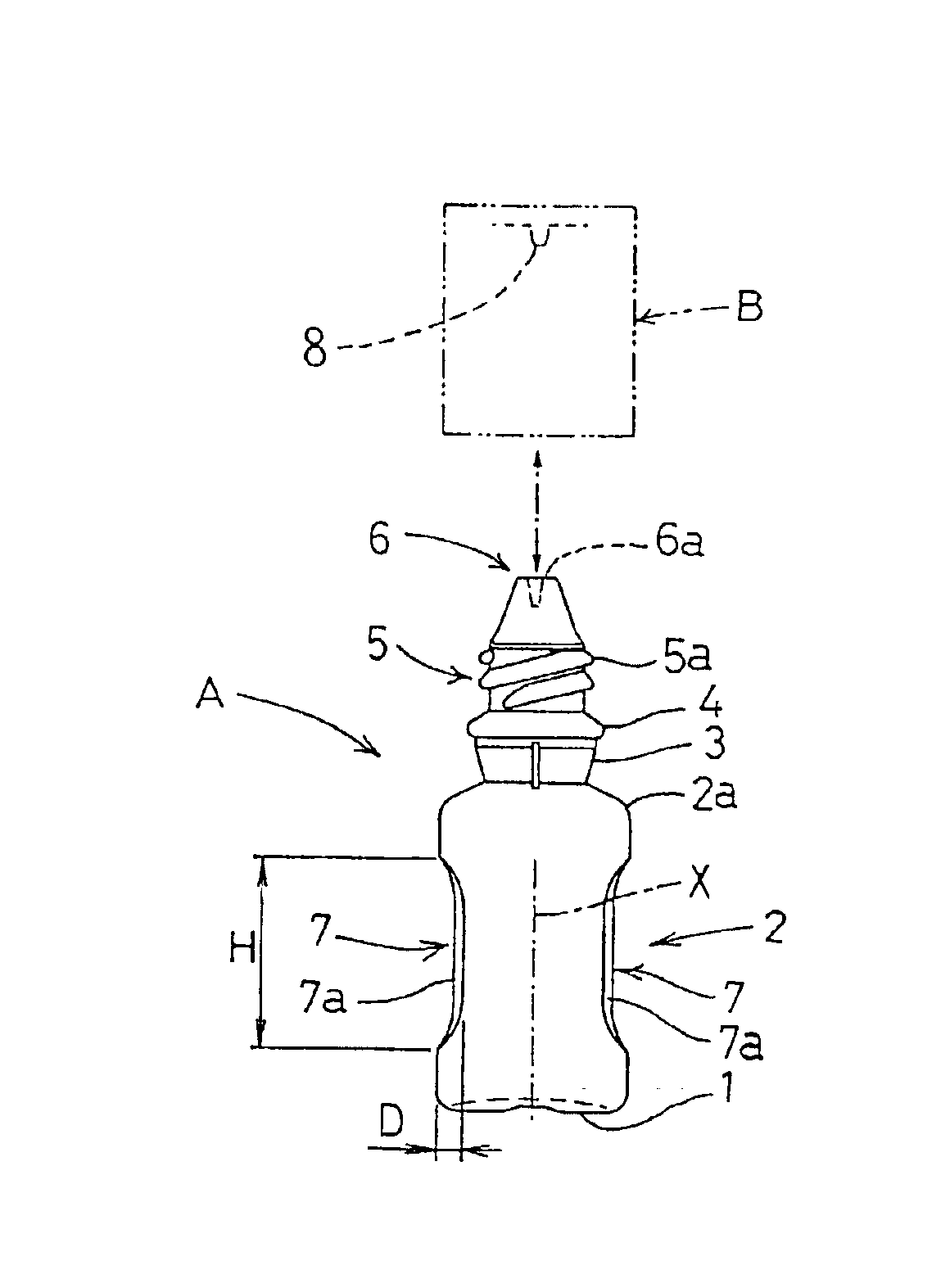
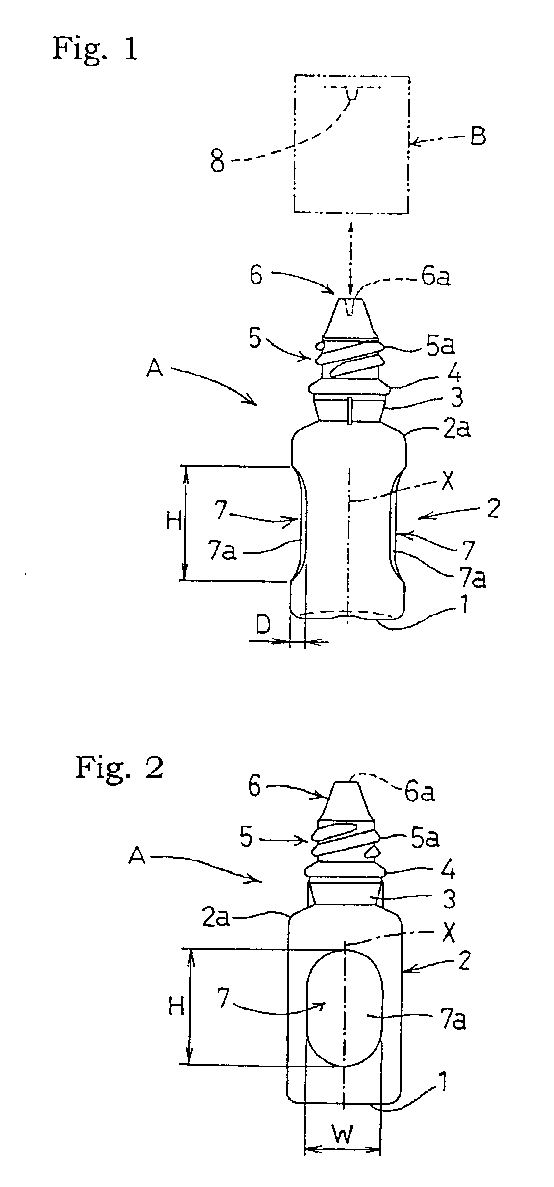
With the above-described characterizing feature, in instilling the solution of medicine from the container body, the dent portion defined in the barrel portion of the container will be gripped with two fingers, so that the gripping position at the tips of the fingers may be maintained in a stable manner. Moreover, when the barrel portion of the container is pressed, the part of this barrel portion contacting the finger tips is dented in advance, so that the force required for the pressing action may be reduced, compared with a case where the part of the cylindrical barrel portion has to be deformed against the elastic resilience.
Accordingly, although the arrangement comprises the simple and inexpensive modification of forming a dent portion in the hollow cylindrical barrel portion, the eye drops container is easier to be gripped and provides superior squeezability with reduced pressing force required. Consequently, there has been achieved an eye drops container having a dent portion easier to use which dropper allows accurate and easy instillation of a solution of medicine from the container.
With the above feature, when the barrel portion of the container body is to be gripped with two fingers, this is done by gripping the flat or substantially flat gripping faces at the two portions of the barrel portion. Thus, the local feeling of pressure felt by the gripping fingers may be reduced, whereby the gripping ease may be further increased.
With the above feature, when the barrel portion of the container body is to be gripped with two fingers, this is done by gripping the curved concave gripping faces which are formed along the curved surfaces of the fingers. Thus, the local feeling of pressure felt by the gripping fingers may be non-existent or substantially non-existent, whereby the gripping ease or comfort may be further increased.
With the above feature, for eye drops containers for medical use of which manufacture cost reduction is required too, the gripping ease and the squeezability may be improved while achieving the manufacture cost reduction required.

Problems solved by technology

However, a person with weak physical strength for the pressing action, such as an aged person, will often find it difficult to control the pressing action.
Further, such person with weak gripping strength, such as an aged person, may find it difficult also to maintain the finger gripping position in a stable manner.

Method used


Image

  • Recessed part forming instillation container
  • Recessed part forming instillation container
  • Recessed part forming instillation container

Examples


Embodiment Construction

For more detailed description thereof, the present invention will be described with reference to accompanying drawings.

[First Mode of Embodiment]

FIGS. 1 through 5 show an eye drops container having a dent portion according to the present invention mainly for use in medical treatment. The dropper includes a container body A made of thermoplastic resin material and charged with a predetermined amount of a solution of medicine therein simultaneously with the blow molding or vacuum molding thereof, and a cap B detachably threaded to a male thread 5a of a threaded cylindrical portion 5 of the container body A.

The container body A includes a circular bottom 1 which is curved inwardly, a hollow cylindrical barrel portion 2 extending continuously from its peripheral edge, a cylindrical neck portion 3 extending continuously from a shoulder 2a of the barrel portion 2, a circular ring-like stepped portion 4 extending radially outward from an upper portion of the neck portion 3, the threaded cy...


PUM


Abstract

In an eye drops container, a barrel portion 2 in the form of a flexible hollow cylinder defines a dent portion 7 which can be gripped with two fingers.

Description

TECHNICAL FIELDThe present invention relates to an eye drops container for containing a solution of medicine therein, and more particularly to an eye drops container composed of a hollow cylinder having flexibility at least at a barrel portion thereof.BACKGROUND ARTAs conventional eye drops containers, especially eye drops containers for medical use, hollow cylindrical containers are widely in use. For instance, a container composed of a hollow cylindrical container body with an inner nozzle tip attached thereto and a container unitary molded a barrel portion of its container body and a liquid instilling portion by means of the blow molding method or vacuum molding method are currently available (see Japanese published utility model gazette No. Sho. 39-11991 for example). Further, as material forming the container, soft thermoplastic resin is generally employed for readiness of its molding.With the eye drops containers of the above-noted type, for instilling the solution of medicine...

Claims


Application Information

Patent Timeline
IPC IPC(8): A61F9/00B65D23/10B65D1/08
CPCA61F9/0008B65D1/08G01F11/082B65D47/18B65D23/102
Inventor KAWASHIMA, YOICHIKUSU, YUKIOYAMADA, HIROSHI
Owner SANTEN PHARMA CO LTD
Learn More