
Controller for electric power steering system

a technology of electric power steering and controller, which is applied in the direction of steering components, power driven steering, position/direction control, etc., can solve the problems of not being able to perform preferable assist, not being able to obtain the necessary resolution, amplifying and increasing the latent offs

Inactive Publication Date: 2005-04-05
NSK LTD
View PDF11 Cites 6 Cited by
  • Summary
  • Abstract
  • Description
  • Claims
  • Application Information

AI Technical Summary

Benefits of technology

The present invention is made to solve the above problems and its object is to provide a controller for an electric power steering system capable of balancing a steering assist force by correcting the offset of a motor current detecting system and improving the steering feeling.
Moreover, the above object of the present invention is more effectively achieved by storing the offset value in a storing portion, or automatically correcting the offset in accordance with the added value of a standard offset value according to a designed value and the difference between the offset value and the standard value, or storing the difference between the offset value and the standard value according to the designed value in the storing portion and automatically correcting the offset in accordance with the added value of the standard value and the stored value.

Problems solved by technology

Therefore, when using the above high-gain amplifier, a problem occurs that a latent offset is also amplified and increased.
When the above offset is present, a problem occurs that a current seems to flow though the current does not actually flow and thereby, a preferable assist cannot be performed.
However, when a large offset is generated, problems occur that a necessary resolution is not obtained but a scale much larger than a scale necessary for control must be set and only a performance far behind a performance which can be originally realized to correct an offset can be realized.
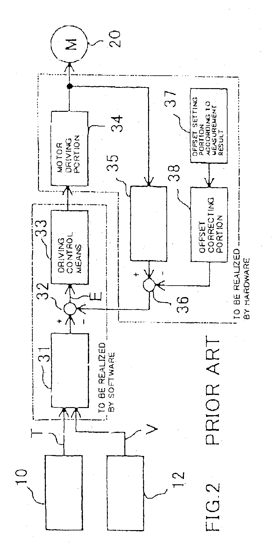
Moreover, as shown in FIG. 2, a system provided with components(the current detecting portion 35, the offset setting portion 37 and the offset-correcting portion 38) capable of previously correcting an offset by the hardware has problems that an extra circuit is necessary to adjust the system, it takes a lot of time to adjust the system, and the manufacturing cost is increased in any case.
Furthermore, to realize an electric power-steering system having a higher performance, it is necessary to further raise the resolution of a current detecting circuit and thereby, the resolution of offset correcting means must be raised, and thus, it is necessary to more severely adjust the offset correcting means.
That is, because an offset is conventionally corrected by hardware, a circuit for correction is necessary, excessive component cost and mounting area are necessary and moreover, man-hours for the correction are necessary and therefore, the cost for adjusting the circuit is increased.
Furthermore, there is a problem that when using a variable resistor(trimmer) in order to realize a correcting circuit, an adjustment error becomes small but a positional shift after adjustment may occur.
On the other hand, when using an adjusting resistor(selection of fixed resistor) in order to realize a correcting circuit, there is a problem that an adjustment error becomes large though no shift occurs after adjustment.
Because of selection from a commercial fixed resistor in variation, there is a disadvantage that it is impossible to adjust a value smaller than the difference width between commercial resistors.

Method used


Image

  • Controller for electric power steering system
  • Controller for electric power steering system
  • Controller for electric power steering system

Examples


second embodiment

FIG. 6 shows the present invention in relation to FIG. 4, which has a configuration of storing a measured offset value in a offset-value-storing portion(such as a nonvolatile memory) serving as an external storage device. In this case, because the offset value of hardware is decided when fabricated, measurement of an offset is stably performed under fabrication by using a configuration of storing a measured offset value only once under fabrication and it is possible to suppress the influence of disturbance(noise or power source fluctuation, etc.) and realize stable correction at a high accuracy.

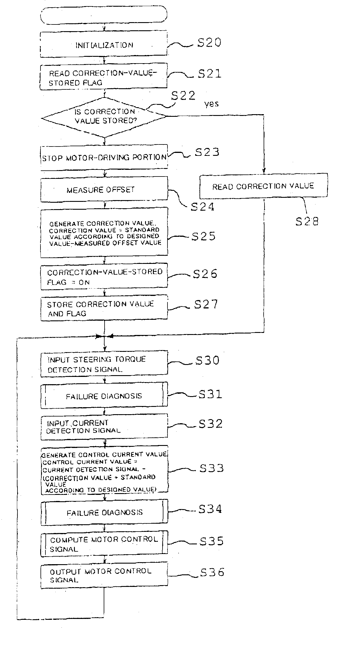
Operations of the second embodiment are described below by referring to the flowchart in FIG. 7.

Initialization is first performed by software(Step S60) and a correction-value-stored flag is read from an offset-value-storing portion 58(Step S61) to determine whether a correction value is stored(Step S62). When it is determined that the correction value is stored, an offset correction value is ...


PUM


Abstract

To provide a controller for an electric power steering system capable of balancing a steering assist force by correcting an offset and improving the steering feeling. A controller for an electric power steering system having motor driving means for driving a motor for electric power steering and motor current detecting means for detecting a current running through the motor is used in which the motor-driving means realizes a motor stop state in which no current runs through the motor under a non-energized state, uses a motor current detection signal under the motor stop state as the offset value of the motor current detecting means, and automatically corrects the offset of the motor current detecting means in accordance with the offset value.

Description

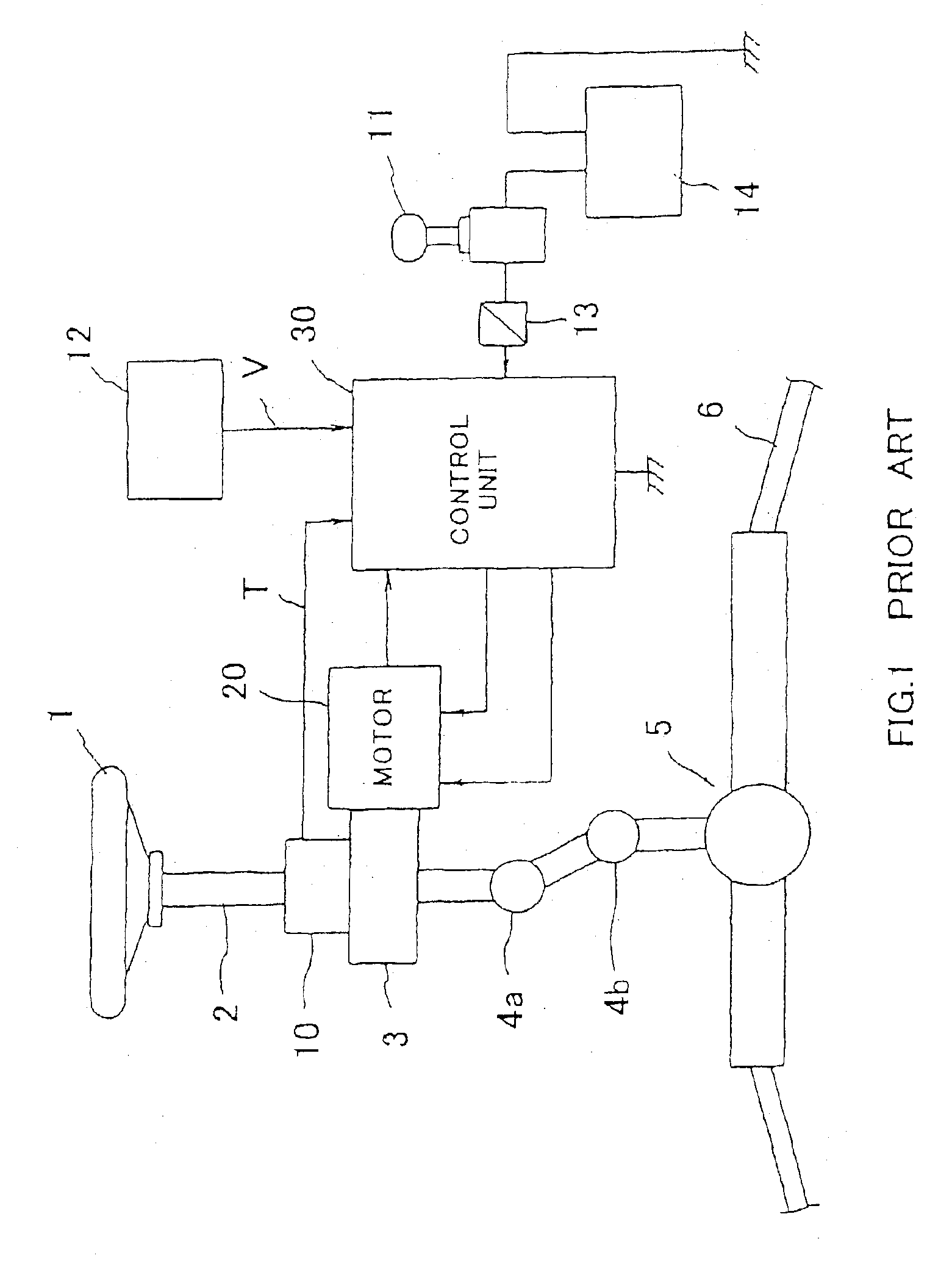
BACKGROUND OF THE INVENTION1. Field of the InventionThe present invention relates to a controller for an electric power steering system for providing a steering assist force by a motor to steering systems of an automobile or a vehicle, particularly to a controller for an electric power steering system for automatically correcting an offset of a motor-current detection system and balancing the steering assist force so as to improve the steering feeling.2. Description of the Prior ArtAn electric power steering system for auxiliary-load-energizing the steering system of an automobile or a vehicle with the rotating force of a motor is designed to energize an assist force to a steering shaft or a rack shaft by a transmission mechanism such as a gear or a belt through a decelerator. This conventional electric power steering system performs feedback control of a motor current in order to accurately generate an assist torque(steering auxiliary torque). The feedback control adjusts a motor-a...

Claims


Application Information

Patent Timeline
Patent Type & Authority Patents(United States)
IPC IPC(8): B62D5/04B62D101/00B62D6/00B62D119/00B62D137/00
CPCB62D5/0481B62D5/0457
Inventor ITAKURA, YUSUKEKOIWAI, HISAYOSHI
Owner NSK LTD
Learn More