
Device for controlling a power output stage

Inactive Publication Date: 2005-03-29
ROBERT BOSCH GMBH
View PDF4 Cites 4 Cited by
  • Summary
  • Abstract
  • Description
  • Claims
  • Application Information

AI Technical Summary

Benefits of technology

An object of the present invention is to provide a power output stage control which further increases the EMV compatibility and decreases the power loss.
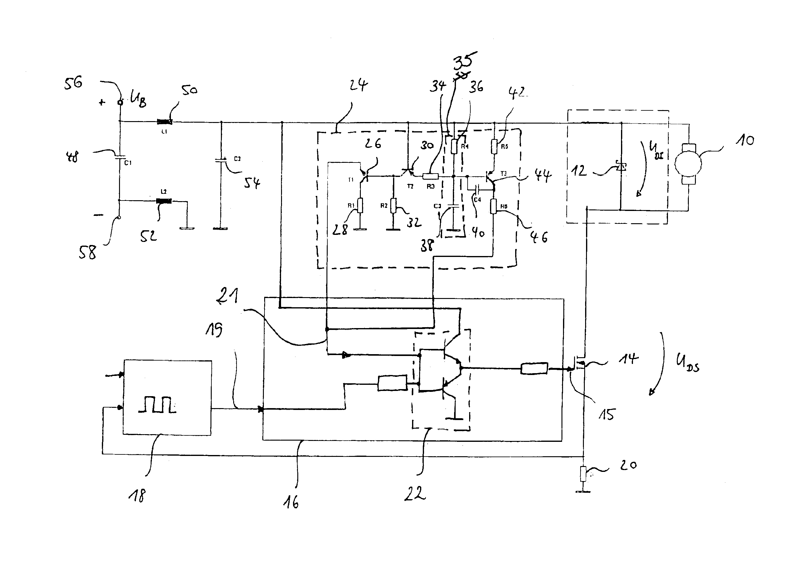
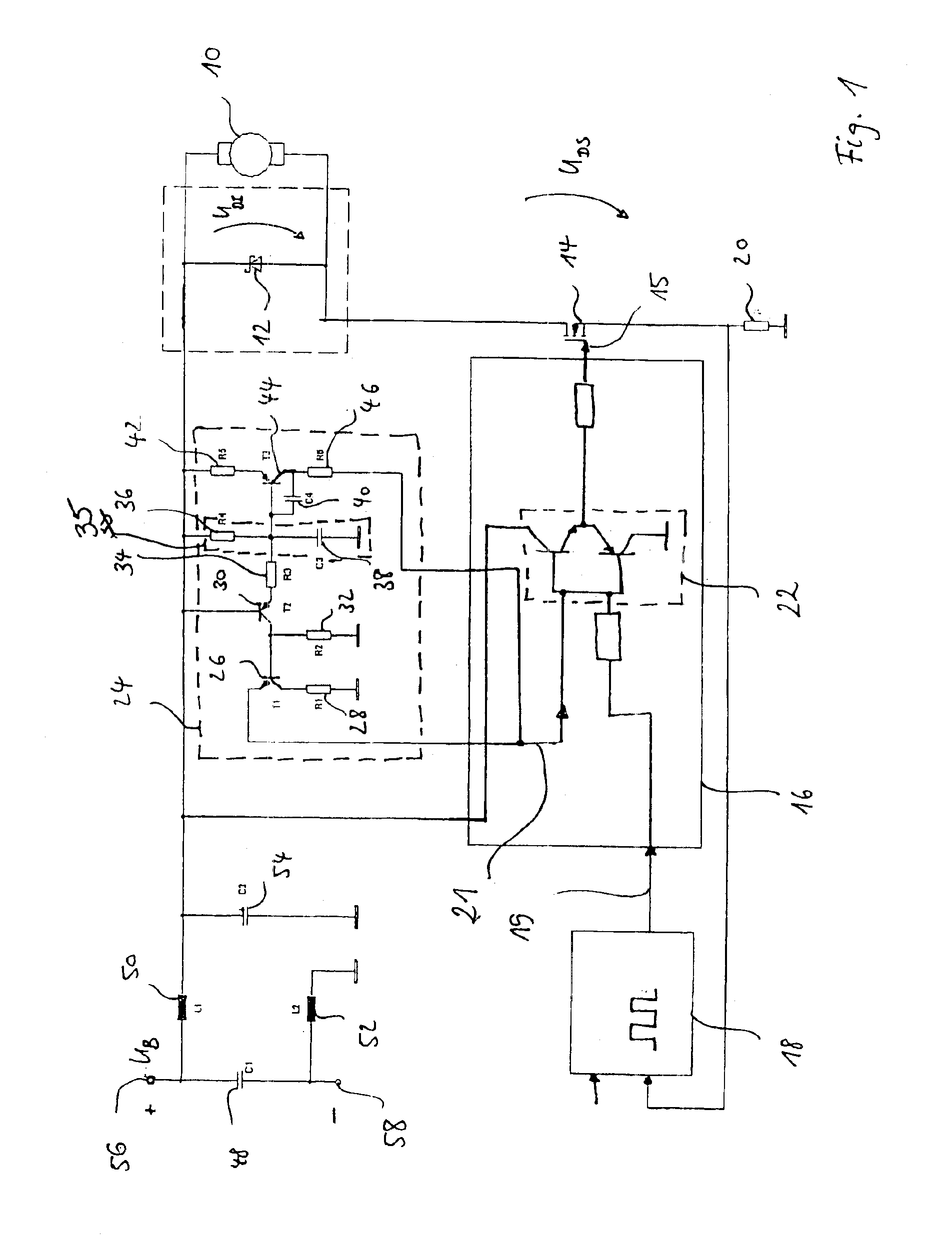
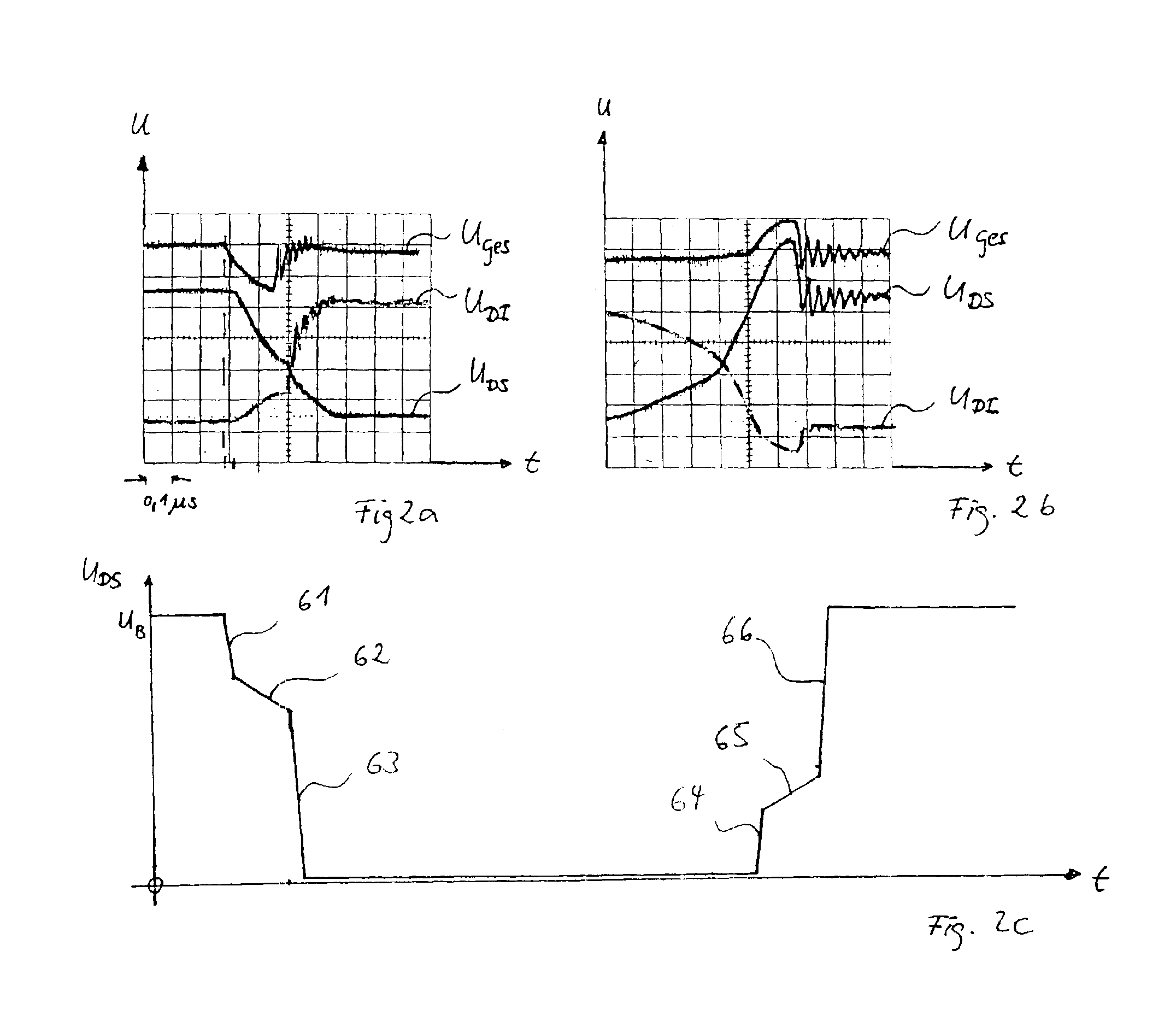
The present invention relates to a device for controlling a power output stage which may generate a trigger signal for at least one power output stage, as a function of at least one control signal, in order to trigger the power output stage, in a switching operation, which may switch an electric load having an inductive component, which may have a recovery diode, for example. The device may further include a detection unit which may acquire a measure for the electrical magnitude applied to the load. It may be distinguished by having a feedback system provided, which may supply at least one feedback signal to the power output stage control, as a function of the measure for the electrical magnitude, for influencing the trigger signal. Because of this, both line-conducted and radiated interferences, particularly with pulse-width modulated power controllers for inductive loads in motor vehicles, may be further reduced, since the feedback may permit an optimized triggering of the power semiconductor. Interferences may be caused by high-frequency, steep-skirted switching on and off, in particular, by the time delays during transition from conducting operation to blocking operation, or vice versa, in a recovery diode connected in parallel to an electromotor. This time delay of the recovery diode at the transition from conducting operation to blocking operation, and vice versa, may be detected with the aid of a voltage dip or a voltage increase and may be used for a failure-optimized triggering of the power output stage. At the times of the transition from the conducting to the nonconducting state of the recovery diode, the steepness of curve of the drain voltage of the power output stage may be reduced in a controlled manner. This may be achieved by the feedback system, which may send a feedback signal on to the power output control, so that the response time of the power output stage may become slower during the transition time. At times when the switching action of the diode is finished, the power output stage may be triggered so as to reduce the overall power loss at maximal response time, i.e. at maximal steepness of curve.

Problems solved by technology

Interferences may be caused by high-frequency, steep-skirted switching on and off, in particular, by the time delays during transition from conducting operation to blocking operation, or vice versa, in a recovery diode connected in parallel to an electromotor.
If, however, the switching action of the diode is finished, the feedback activating device may detect this with the aid of the decline of the voltage increase or the voltage dip, and may deactivate the passing on of the feedback signal.

Method used


Image

  • Device for controlling a power output stage
  • Device for controlling a power output stage
  • Device for controlling a power output stage

Examples


Embodiment Construction

An inductive load 10 is provided as the electrical load, such as an electromotor. A recovery diode 12 is connected in parallel to this inductive load 10. Inductive load 10 is connected via power output stage 14. For the detection of the current flowing through power output stage 14, a measuring resistor 20 connected to ground is provided, whose potential is picked off and supplied to a PWM control 18. A setpoint value is also supplied to this PWM control 18. From the setpoint value and the actual value, PWM control 18 generates a control signal which is used by a power output stage control 16 as an input variable. Power output control 16 includes a push-pull stage 22, made up of two transistors whose respective bases are connected to each other in an electrically conducting manner. Both control signal 19 via a series resistor and a feedback signal 21 are supplied to the base of push-pull stage 22 in an electrically conducting manner. Push-pull stage 22 is fed by positive supply volt...


PUM


Abstract

A control device for a power output stage is proposed, which includes a power output stage control which generates a triggering signal as a function of at least one control signal, for triggering at least one power output stage, which switches an electric load, preferably an inductive load having a recovery diode, a recording device being provided which records a measure for an electrical magnitude, which is applied to electric load. A feedback system is also provided, which supplies the power output stage control with at least one feedback signal as a function of the measure for the electrical magnitude, so as to influence the trigger signal.

Description

FIELD OF THE INVENTIONThe present invention is based on a device for controlling a power output stage.BACKGROUND INFORMATIONA power output stage circuit having PWM (pulse-width modulation) operation and permanently closed operation is described in European Patent Application No. 899 860. A series-connected control circuit controls the pulse-width modulation generator and the power output stage into a permanently open state, a PWM operation having pulse-width modulated pulses and a permanently closed state, as a function of an externally predefined setpoint value, an actual value of the power output stage, and a reference voltage derived from the supply voltage. An increased power loss and a high EMV (electromagnetic compatibility) in the extreme range toward full load output may be avoided by the feature that it goes over prematurely from PWM operation to permanently closed operation as a function of a predefined setpoint value and of the supply voltage, and through a hysteresis of ...

Claims


Application Information

Patent Timeline
IPC IPC(8): H02M3/04H02M3/156H02P7/18H02P7/288
CPCH02P7/288H02M3/156H02M1/44H02M2003/1555H02M3/1555
Inventor SEYFANG, BERNDEISENHARDT, HARALDPRANG, MICHAEL
Owner ROBERT BOSCH GMBH
Learn More