
Optical frequency sweep control and readout by using a phase lock

a phase lock and optical frequency technology, applied in the direction of optical apparatus testing, optical radiation measurement, instruments, etc., can solve the problems of excessively limited operational wavelength range, inconvenient operation, and inability to characterize optical networking components,

Inactive Publication Date: 2005-03-22
PRECISION PHOTONICS CORP
View PDF3 Cites 77 Cited by
  • Summary
  • Abstract
  • Description
  • Claims
  • Application Information

AI Technical Summary

Benefits of technology

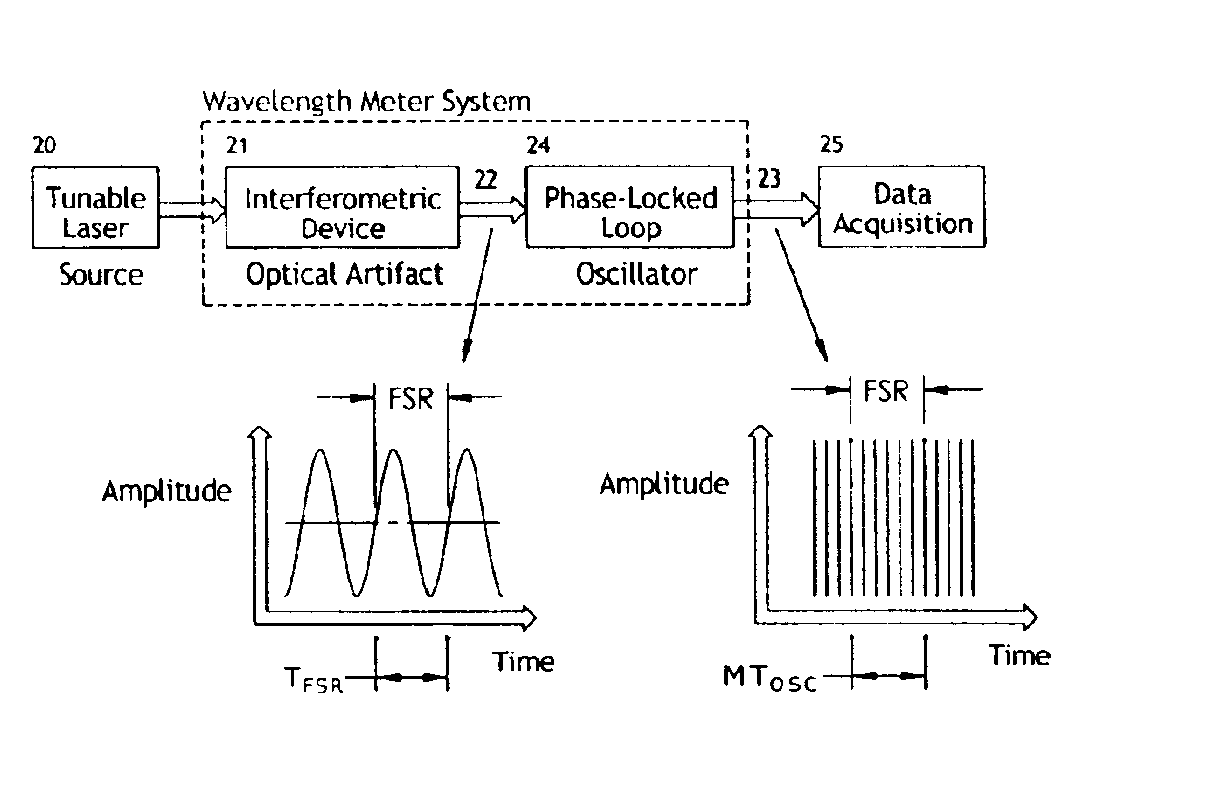
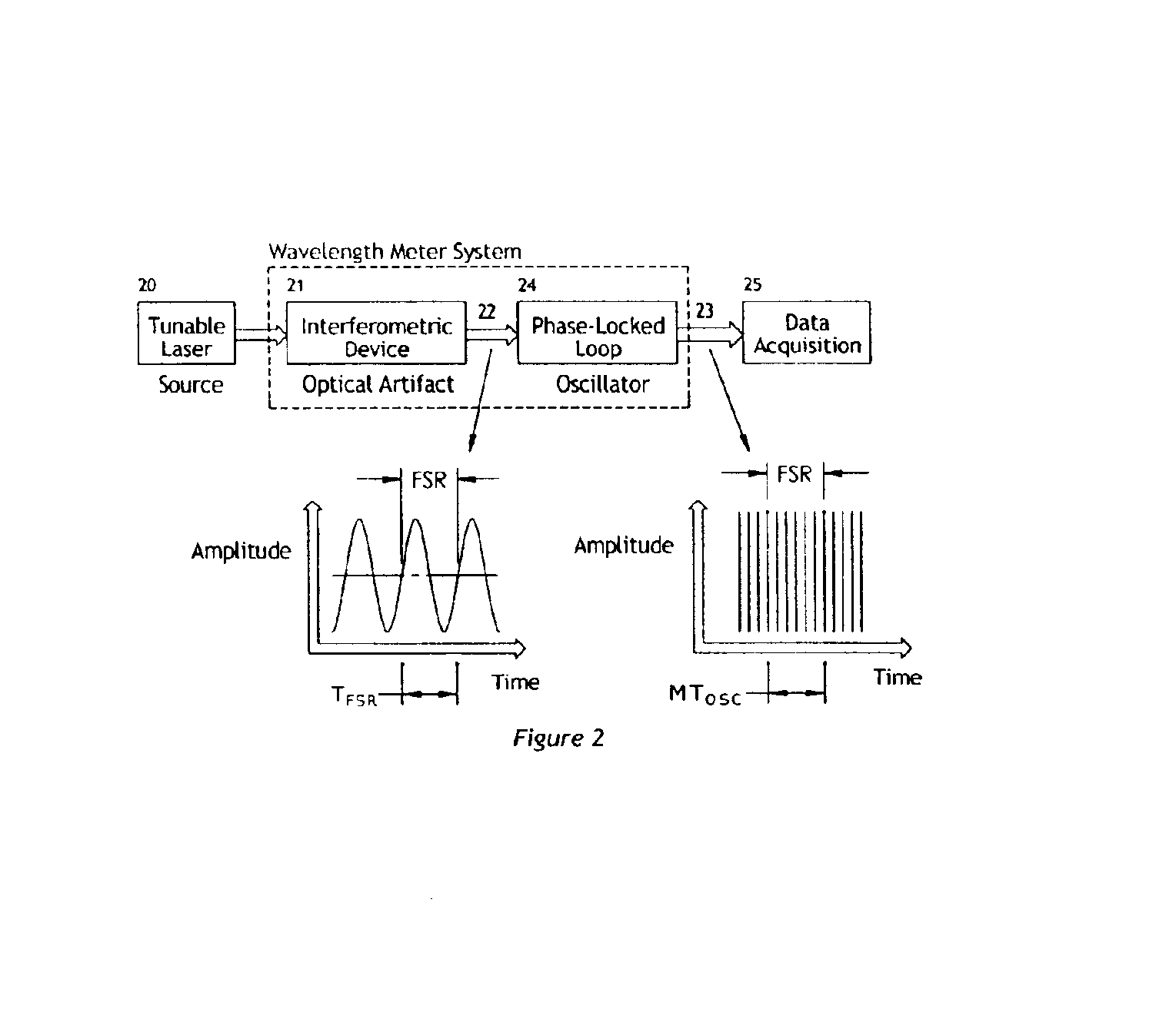
[0016]The optical frequency reference may be selected from a group consisting of an atomic / molecular gas cell, an optical fiber Bragg grating, an optical thin-film filter, and a low-thermal expansion etalon. The optical frequency of each oscillator tick may be determined from a known calibration of the FSR of the optical artifact and a known optical frequency reference location during a scan of optical frequency of the source of coherent optical radiation that produces the first optical beam. The optical frequency of each oscillator tick may be determined by correlating oscillator tick locations to two or more known optical frequency reference locations by using a statistical estimation method. Subsequent to a sweep of an optical frequency of the coherent radiation source, frequency errors in an oscillator tick axis may be reduced by making a correction to each oscillator tick frequency location based upon recorded phase errors between the optical artifact signal and the oscillator signal divided in frequency by the multiple.
[0021]The present invention also relates to an optical test system for testing a device under test. The test system includes a source of coherent light that can be controlled to sweep through a range of optical frequencies and a wavelength measurement device receptive of a portion of the light from the light source, the device providing a periodic signal as an output therefrom, the periodic signal having a period that relates to the rate of change of the optical frequency of the light from the light source. The system also includes an interface between the light source and the device under test to provide light thereto, an interface between the device under test and the optical test system for receiving optical or electrical signals therefrom, and a data acquisition system receptive of the optical or electrical energy received from the device under test and receptive of the periodic signal from the wavelength measurement device. The periodic signal allows the data acquisition system to correlate the signals received from the device under test to the optical frequency of the light provided to the device under test.

Problems solved by technology

Many high-resolution techniques exist for very accurate control of laser frequency sweeps, but these techniques are usually for laboratory experiments where size, cost and complexity of the technique are not of primary importance.
A further disadvantage of these techniques is that they are extremely limited in their operational wavelength range and are not useful for characterizing optical networking components.
However, commercial meters are too expensive and too large to fit into other test instruments.

Method used


Image

  • Optical frequency sweep control and readout by using a phase lock
  • Optical frequency sweep control and readout by using a phase lock
  • Optical frequency sweep control and readout by using a phase lock

Examples


Embodiment Construction

errors for each fringe of the optical artifact are determined.

[0033]FIG. 10 illustrates an embodiment in which the laser light is free-space coupled to the wavelength meter system.

[0034]FIG. 11 shows typical signals from some of the components shown in FIG. 10.

[0035]FIG. 12 illustrates a preferred embodiment in which the laser light is fiber-coupled to the wavelength meter system.

[0036]FIG. 13 details the auto-balancing level detection scheme used for detecting power-normalized level crossings of the optical artifact.

[0037]FIG. 14 shows the scheme for controlling the optical frequency scan rate of a laser by feedback of the phase difference between a reference oscillator signal and an optical artifact signal.

[0038]FIG. 15 illustrates an embodiment for feedback control of the optical frequency scan rate of a laser by using free-space coupling of the laser to the wavelength control system.

[0039]FIG. 16(a) depicts an embodiment of an optical spectrum analyzer device.

[0040]FIG. 16(b) sh...


PUM


Abstract

The invention allows for the accurate, real-time readout of the optical frequency of a swept-wavelength laser device by counting the number of fringes of a calibrated etalon that occur as the laser is swept. The distinguishing feature of the present invention is that the etalon fringe signal is phase-locked to a slave signal of a higher multiple frequency. The higher frequency of the slave signal divides the frequency interval of the etalon fringe spacing by the additional frequency multiple. The slave signal therefore generates a scale for optical frequency that is of higher resolution than possible with the etalon alone. The phase-lock also insures that the slave signal tracks monotonic scans of the optical frequency regardless of scan profile.The invention also allows for the precise, real-time control of the optical frequency of a laser during the sweep of the laser. By comparing a signal proportional to the transmission of light through a calibrated Fabry-Perot etalon to a reference control signal, the phase difference between etalon transmission signal and the reference signal may be fed back to the laser to drive the phase difference to zero (phase-lock). The phase-lock ensures that the optical frequency profile of the sweep follows exactly the frequency profile of the reference signal. Tailoring the input reference signal controls the velocity of the optical-frequency sweep.

Description

CROSS-REFERENCE TO RELATED APPLICATIONS[0003]This application claims priority from U.S. Provisional Patent Application No. 60 / 346,009, filed Oct. 29, 2001, entitled “Optical Frequency Sweep Control and Readout using a Phase-Lock” and U.S. Provisional Patent Application No. 60 / 365,406, filed Mar. 18, 2002, entitled “Optical Frequency Sweep Control and Readout using a Phase-Lock,” the contents of each of which are incorporated herein by reference.FIELD OF THE INVENTION[0004]This invention relates to the field of optical frequency control and readout of a coherent radiation source, such as a tunable laser, whose optical wavelength is varied in time from one wavelength to a second wavelength value.BACKGROUND[0005]Accurate control and readout of the optical frequency of a laser is important for many applications such as high-resolution spectroscopy, time and frequency metrology, interferometry and length metrology, optical-based communication, and optical component characterization. Of c...

Claims


Application Information

Patent Timeline
Patent Type & Authority Patents(United States)
IPC IPC(8): G01B9/02G01J9/02G01M11/00
CPCG01M11/331G01J9/0246
Inventor VOGEL, KURT R.DINNEEN, TIMOTHY P.DEEDS, MICHAEL E.ENSHER, JASON R.MYATT, CHRISTOPHER J.
Owner PRECISION PHOTONICS CORP
Learn More