
Thermal barrier coatings with improved impact and erosion resistance

a technology of thermal barrier coating and impact resistance, which is applied in the direction of chemical vapor deposition coating, magnetic recording, record information storage, etc., can solve the problems of coatings being susceptible to various types of damage, components operating in the gas path environment of gas turbine engines are typically subject to significant temperature extremes and degradation, and achieve improved impact and erosion resistance of thermal barrier coating, and desirable thermal conductivity

Inactive Publication Date: 2005-03-22
GENERAL ELECTRIC CO
View PDF28 Cites 58 Cited by
  • Summary
  • Abstract
  • Description
  • Claims
  • Application Information

AI Technical Summary

Benefits of technology

The thermal barrier coatings of this invention provide impact and erosion resistance improvement benefits when used with metal substrates of articles exposed to high temperatures, such as turbine components. This improvement in impact and erosion resistance for the thermal barrier coating can be achieved while allowing flexibility in using a variety of zirconia-containing ceramic compositions that can impart to the thermal barrier coating desirable thermal conductivity properties.

Problems solved by technology

Components operating in the gas path environment of gas turbine engines are typically subjected to significant temperature extremes and degradation by oxidizing and corrosive environments.
Although significant advances have been made in improving the durability of thermal barrier coatings for turbine engine components, such coatings are still susceptible to various types of damage, including objects ingested by the engine, erosion, oxidation, and attack from environmental contaminants.

Method used


Image

  • Thermal barrier coatings with improved impact and erosion resistance
  • Thermal barrier coatings with improved impact and erosion resistance
  • Thermal barrier coatings with improved impact and erosion resistance

Examples


Embodiment Construction

As used herein, the term “zirconia-containing ceramic compositions” refers to ceramic compositions where zirconia is the primary component that are useful as thermal barrier coatings that are capable of reducing heat flow to the underlying metal substrate of the article, i.e., forming a thermal barrier, and which have a melting point that is typically at least about 2600° F. (1426° C.), and more typically in the range of from about from about 3450° to about 4980° F. (from about 1900° to about 2750° C.).

As used herein, the term “fraction of porosity” refers to the volume fraction of porosity defined by unity (i.e., 1), minus the ratio of the actual density of the thermal barrier coating to its theoretical density.

As used herein, the term “comprising” means various compositions, compounds, components, layers, steps and the like can be conjointly employed in the present invention. Accordingly, the term “comprising” encompasses the more restrictive terms “consisting essentially of” and ...


PUM

PropertyMeasurementUnit
thicknessaaaaaaaaaa
thicknessaaaaaaaaaa
thicknessaaaaaaaaaa

Abstract

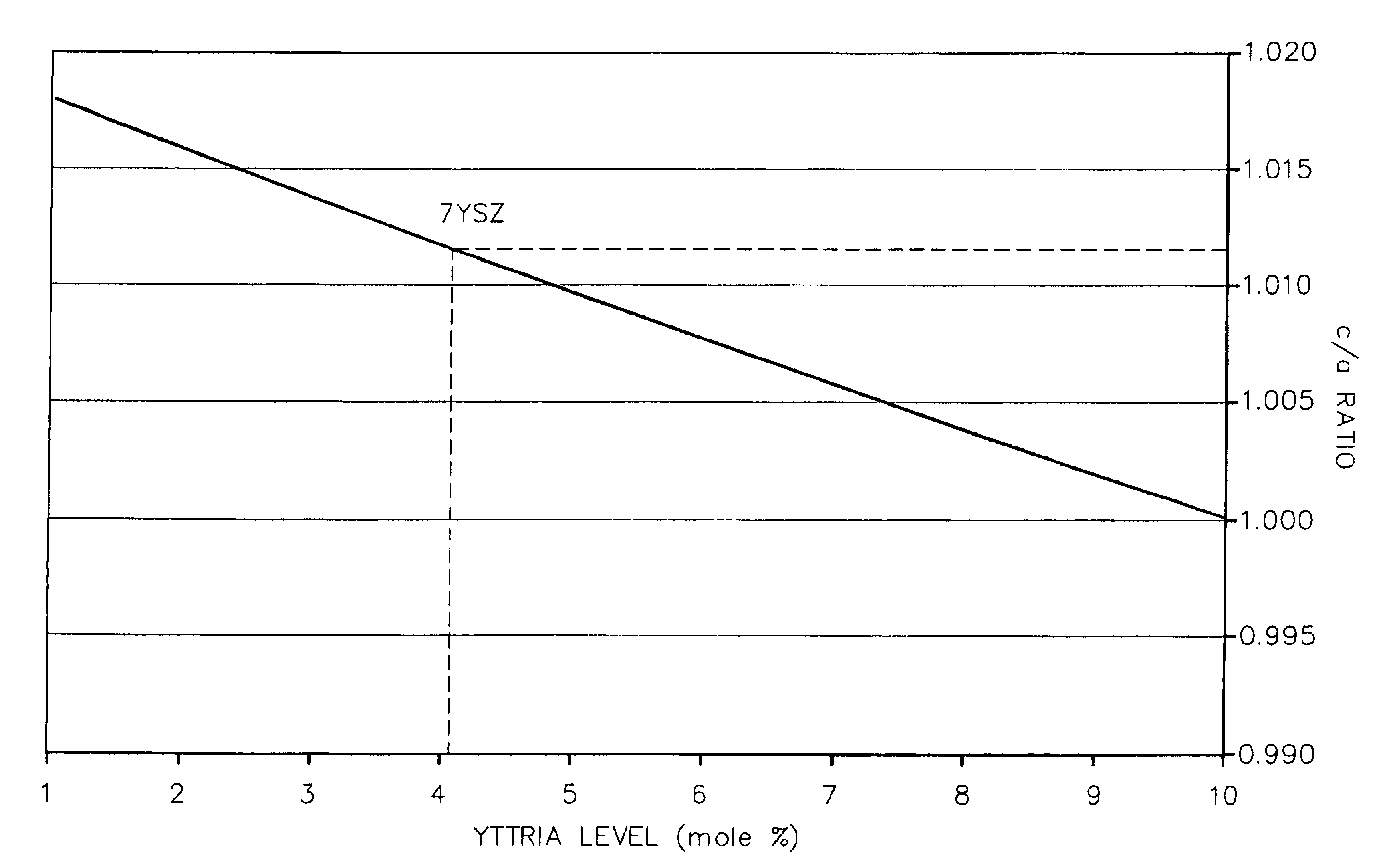
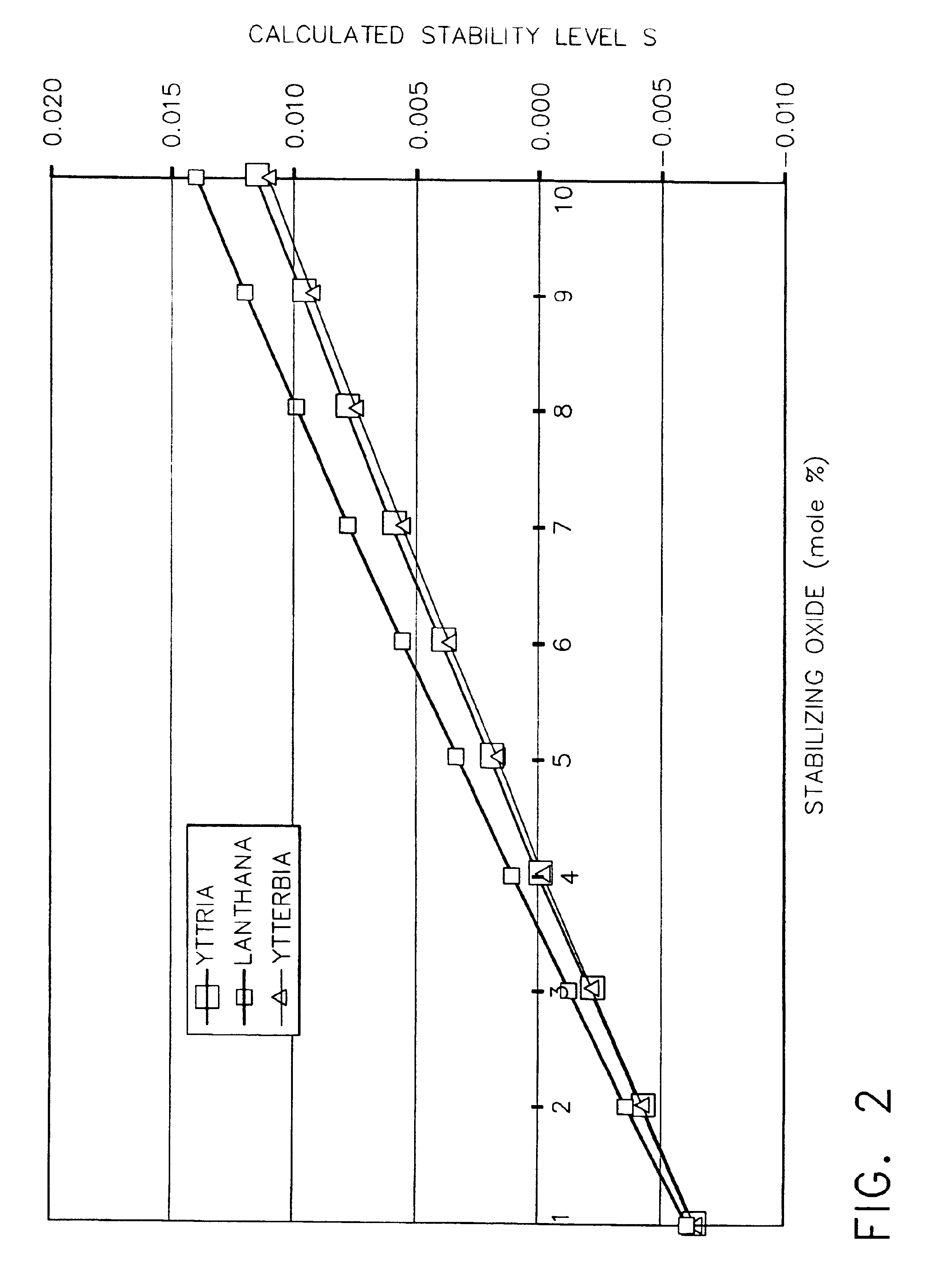
A reduced thermal conductivity thermal barrier coating having improved impact and erosion resistance for an underlying metal substrate of articles that operate at, or are exposed to, high temperatures. This coating comprises a zirconia-containing ceramic composition having a c / a ratio in the range of from about 1.0117 to about 1.0148 and stabilized in the tetragonal phase by a stabilizing amount of a stabilizer metal oxide. The coating has a fraction of porosity of from about 0.10 to about 0.25, and an impact and erosion resistance property defined by at least one of the following formulas: (a) I=exp.[5.85−(144×s)−(3.68×p)]; and / or; (b) E=[187−(261×p)−(9989×s)], wherein s=1.0117−c / a ratio; p is the fraction of porosity; I is least about 140 g / mil; and E is least about 130 g / mil. This coating can be used to provide a thermally protected article having a metal substrate and optionally a bond coat layer adjacent to and overlaying the metal substrate. The thermal barrier coating can be prepared by depositing the zirconia-containing ceramic composition on the bond coat layer, or the metal substrate in the absence of the bond coat layer.

Description

BACKGROUND OF THE INVENTIONThis invention relates to improving the impact and erosion resistance of thermal barrier coatings. This invention further relates to articles having such coatings and methods for preparing such coatings for the article.Components operating in the gas path environment of gas turbine engines are typically subjected to significant temperature extremes and degradation by oxidizing and corrosive environments. Environmental coatings and especially thermal barrier coating are an important element in current and future gas turbine engine designs, as well as other articles that are expected to operate at or be exposed to high temperatures, and thus cause the thermal barrier coating to be subjected to high surface temperatures. Examples of turbine engine parts and components for which such thermal barrier coatings are desirable include turbine blades and vanes, turbine shrouds, buckets, nozzles, combustion liners and deflectors, and the like. These thermal barrier c...

Claims


Application Information

Patent Timeline
Patent Type & Authority Patents(United States)
IPC IPC(8): C23C14/08C23C30/00C23C4/10C23C28/00F01D5/28B32B15/04C23C26/00C23C28/04F02C7/00
CPCC04B35/486C23C4/105C23C28/3215C23C28/3455C23C30/00F01D5/288C04B2235/3206C04B2235/3208C04B2235/3224C04B2235/3225C04B2235/3227Y10T428/12611Y10T428/265C04B2235/761C23C4/11Y10T428/249953
Inventor SPITSBERG, IRENEBOUTWELL, BRETT ALLEN
Owner GENERAL ELECTRIC CO
Learn More