
Apparatus for polishing optical disk

a technology for polishing apparatus and optical disk, which is applied in the direction of manufacturing tools, lapping machines, instruments, etc., can solve the problems of difficult to eliminate abrasive filings, inability to read data from the disk, and inability to dispose of such reusable optical disks in large quantities, so as to improve the polishing efficiency and prevent the occurrence of clogging. , the effect of adequate polishing

Inactive Publication Date: 2005-03-22
ELM CO LTD
View PDF18 Cites 15 Cited by
  • Summary
  • Abstract
  • Description
  • Claims
  • Application Information

AI Technical Summary

Benefits of technology

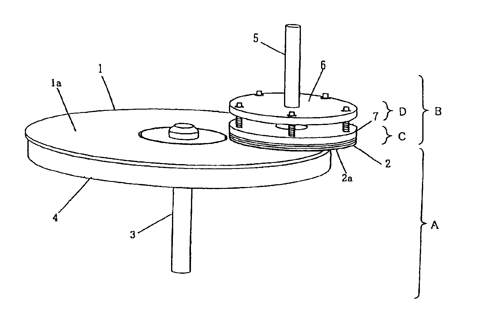
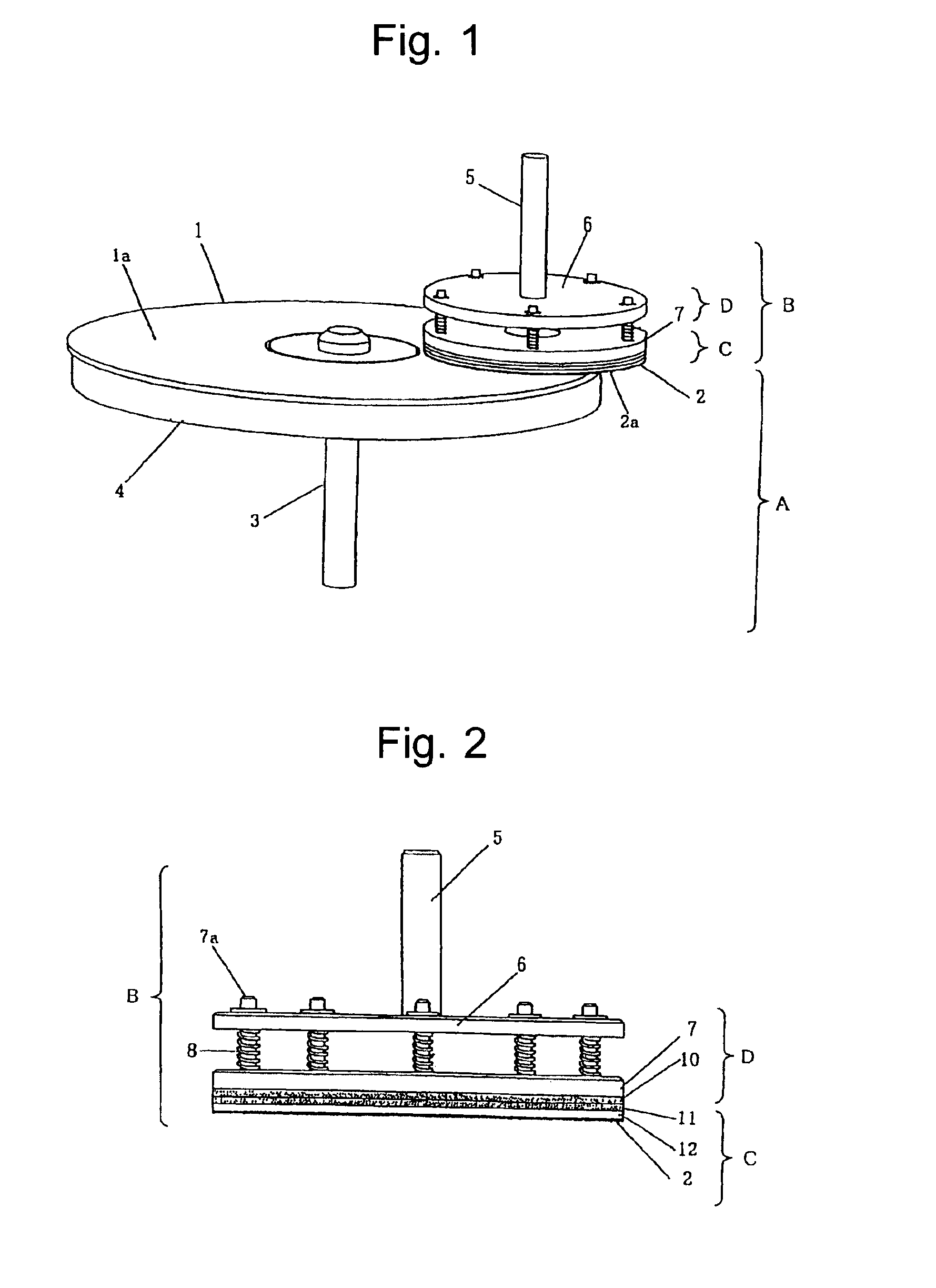
[0010]In this invention, it is possible to prevent clogging of the surface of the polishing sheet by the active elimination of abrasive filings and an occurrence of scratches on the surface of the optical disk due to the clogging. It is also possible to remove roundness formed on the outer edge of the optical disk and unevenness in polishing by regulating elasticity of the polishing sheet.
[0012]In this invention, it is possible to correct the accuracy of parallelism between the rotation planes of the optical disk and the polishing sheet. Thereby, the pressure contact between the polishing face and the surface of the optical disk can be appropriately equalized. Thus, it is possible to remove roundness formed on the outer edge of the optical disk and unevenness in polishing.
[0014]In this invention, it is possible to increase the polishing efficiency and thus obtain an adequate amount of polishing by setting the ratio of the disk angular speed of the disk rotator A and the polishing sheet angular speed of the polishing mechanism B within a predetermined range. It is also possible to prevent an occurrence of clogging by facilitating the elimination of filings. Further, endurance of the polishing sheet can be improved.

Problems solved by technology

When a flaw or flaws are made on its surface, it is sometimes impossible to read data from the disk.
In view of resource saving, it is not desirable to dispose of such reusable optical disks in large quantities.
It is therefore difficult to eliminate abrasive filings (e.g. polycarbonate powder), which clog the surface of the polishing sheet.
Thus, the polishing power decreases and the accumulated filings cause small shallow cuts (i.e. scratches) on the surface of the optical disk.
Further, when the rotation plane of the optical disk is not kept parallel to that of the polishing sheet 36, it is impossible to adequately correct the planar accuracy of the polished face in the course of polishing, as shown in FIG. 6b.

Method used


Image

  • Apparatus for polishing optical disk
  • Apparatus for polishing optical disk
  • Apparatus for polishing optical disk

Examples


experiment example 1

[0034]The polishing pads were prepared by using the elastic sheets that differed in material and thickness. Next, these polishing pads were attached to the polishing mechanism B of the polishing apparatus according to the present embodiment. The surface of the polishing sheet of each polishing pad was pressed into contact with the surface of the optical disk with a pressure required for polishing. Samples 1-6 were thus obtained. Reference is made to Table 1, which shows the deformation amount Δx of the surface of the polishing sheet in this case. Table 1 also shows the comprehensive as well as the individual rating regarding clogging of the surface of the polishing sheet and roundness formed on the outer edge of the optical disk. In the present experiment, the rotation speed of the disk rotator A is 500 rpm and that of the polishing mechanism B is 1200 rpm. The disk rotator A and the polishing mechanism B rotate in the same direction.

[0035]In the sample 1, the polishing sheet is dir...

experiment example 2

[0037]With the polishing apparatus according to the present embodiment, the disk angular speed ωa of the disk rotator A and the polishing sheet angular speed ωb of the polishing were regulated to set the angular speed ratio at the values shown in Table 2. Samples 1-7 were thus obtained. As for these samples, an amount of polishing was measured. In the meantime, the elimination of filings, an occurrence of clogging, etc. were rated. These measurement and ratings are comprehensively shown in the column of “Rating of Amount of Polishing ” of Table 2.

TABLE 2Disk Angular Speed / Polishing SheetRating ofSampleAngular SpeedAmount ofNo.(ωa / ωb)Polishing10.1X20.2Δ30.4◯40.6⊚51.0◯61.5Δ72.0X

[0038]As for the sample No. 1 (ratio of 0.1) where the disk angular speed is low and the polishing sheet angular speed is high, the polishing sheet always effects polishing in the direction La parallel to a trace of polishing Ka, as shown in FIG. 7a. In this case, while the same abrasive grains of the polishing...


PUM

PropertyMeasurementUnit
elasticityaaaaaaaaaa
pressureaaaaaaaaaa
rigidityaaaaaaaaaa

Abstract

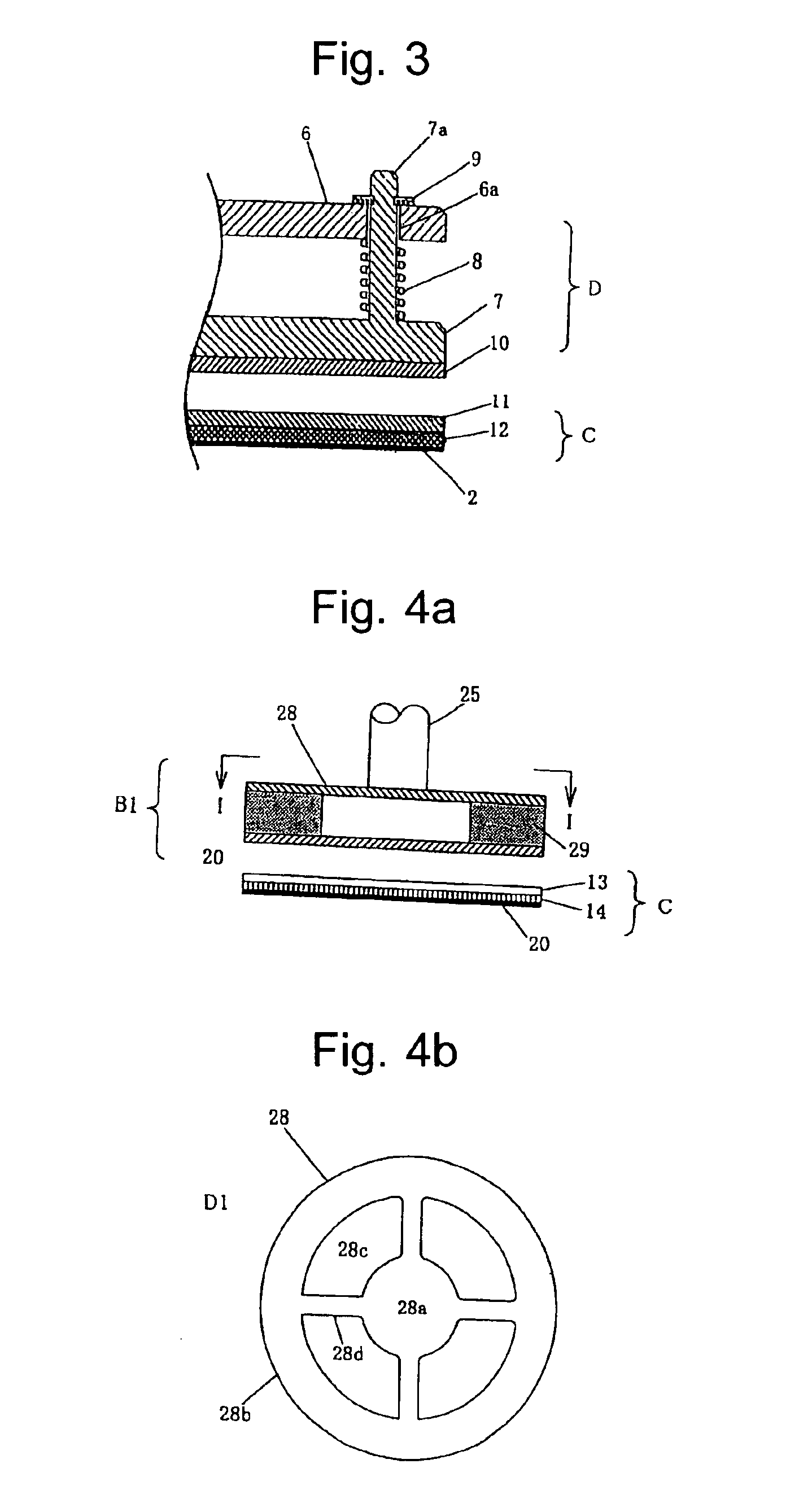
The present invention relates to a polishing apparatus for restoring an optical disk. The objects of the present invention are as follows: to obtain an equal pressure appropriately required for polishing; to correct the accuracy of parallelism between the rotation planes of an optical disk and a polishing sheet; to remove roundness formed on the outer edge of an optical disk and unevenness in polishing; and to prevent clogging of the surface of a polishing sheet by the active elimination of abrasive filings and an occurrence of scratches on the surface of an optical disk due to the clogging. For the purpose of achieving the above objects, in an apparatus for polishing an optical disk composed of a disk rotator A and a polishing mechanism B, the polishing mechanism B has an elastic mechanism D for elastically holding a polishing pad C, a polishing sheet of the polishing pad C has such an elasticity that the deformation amount Δx is 0.005 mm to 0.3 mm when the polishing sheet contacts the surface of the optical disk with a pressure required for polishing, the elastic mechanism D is constructed to have elasticity in the direction perpendicular to the rotation plane of the optical disk and rigidity in the direction parallel to the rotation plane of the optical disk, and the ratio of the disk angular speed ωa of the disk rotator A to the polishing sheet angular speed ωb of the polishing mechanism B is regulated to satisfy the range of 0.2<ωa / ωb<1.5.

Description

TECHNICAL FIELD[0002]The present invention relates to a polishing apparatus for restoring optical disks, such as CD, DVD, VD and LD.BACKGROUND ART[0003]Recently, optical disks have been selling in large quantities. When a flaw or flaws are made on its surface, it is sometimes impossible to read data from the disk. It is therefore desirable to repair the disk and restore it to a readable state. In view of resource saving, it is not desirable to dispose of such reusable optical disks in large quantities.[0004]Reference is made to FIG. 5, which shows an example of a conventional disk polishing apparatus. The apparatus is composed of a disk rotator A2 for rotating an object 31 and a polishing mechanism B2 for polishing the surface of the object 31. In the polishing mechanism B2, a polishing pad C2 is attached to a rotating substrate 33 fixed to a rotation shaft 32 via such an attachment means as the hook-and loop fastener VELCRO™. In the polishing pad C2, a polishing sheet 36 is attache...

Claims


Application Information

Patent Timeline
Patent Type & Authority Patents(United States)
IPC IPC(8): B08B1/04B24B29/00B24B37/04B24B41/06B24B7/22B24B7/20B24B9/06B24B9/08G11B23/50B29B17/02
CPCB24B7/228G11B23/505B24D13/20B24D13/14
Inventor MIYAHARA, TAKAKAZUGENOZONO, JIRO
Owner ELM CO LTD
Learn More