
Manufacturing method of diamond cutter

Inactive Publication Date: 2005-03-22
RIKEN DAIYAMONDO INDS
View PDF11 Cites 4 Cited by
  • Summary
  • Abstract
  • Description
  • Claims
  • Application Information

AI Technical Summary

Benefits of technology

Accordingly, an object of the present invention is to provide a method of manufacturing a diamond cutter by which a cutter base plate having a curved surface being wholly point symmetrical about an axial hole, such as a parabolic antenna shape or the like, can be easily and simply manufactured between the axial hole and an outer shape, therefore manufacturing cost can be made low, and a strength capable of sufficiently standing against a load at a cutting time is provided to the cutter base plate.

Problems solved by technology

However, there are problems such that a rotational oscillation is easily generated at a time of rotating on its own axis and moving around the center because the cutter base plate is flat, and it is hard to smoothly move around the center due to the flat cutter base plate.
Accordingly, in accordance with the conventional art mentioned above, since the base plate is formed by scraping the material having the comparatively high hardness so as to have the curved surface between the axial hole and the outer shape, there are problems that a stock utilization is low, a lot of trouble is taken for manufacturing, a lot of skill is required for a scraping process, and a manufacturing cost is high.

Method used


Image

  • Manufacturing method of diamond cutter
  • Manufacturing method of diamond cutter
  • Manufacturing method of diamond cutter

Examples


Embodiment Construction

A description will be given next of a preferable embodiment in accordance with the present invention with reference to the accompanying drawings.

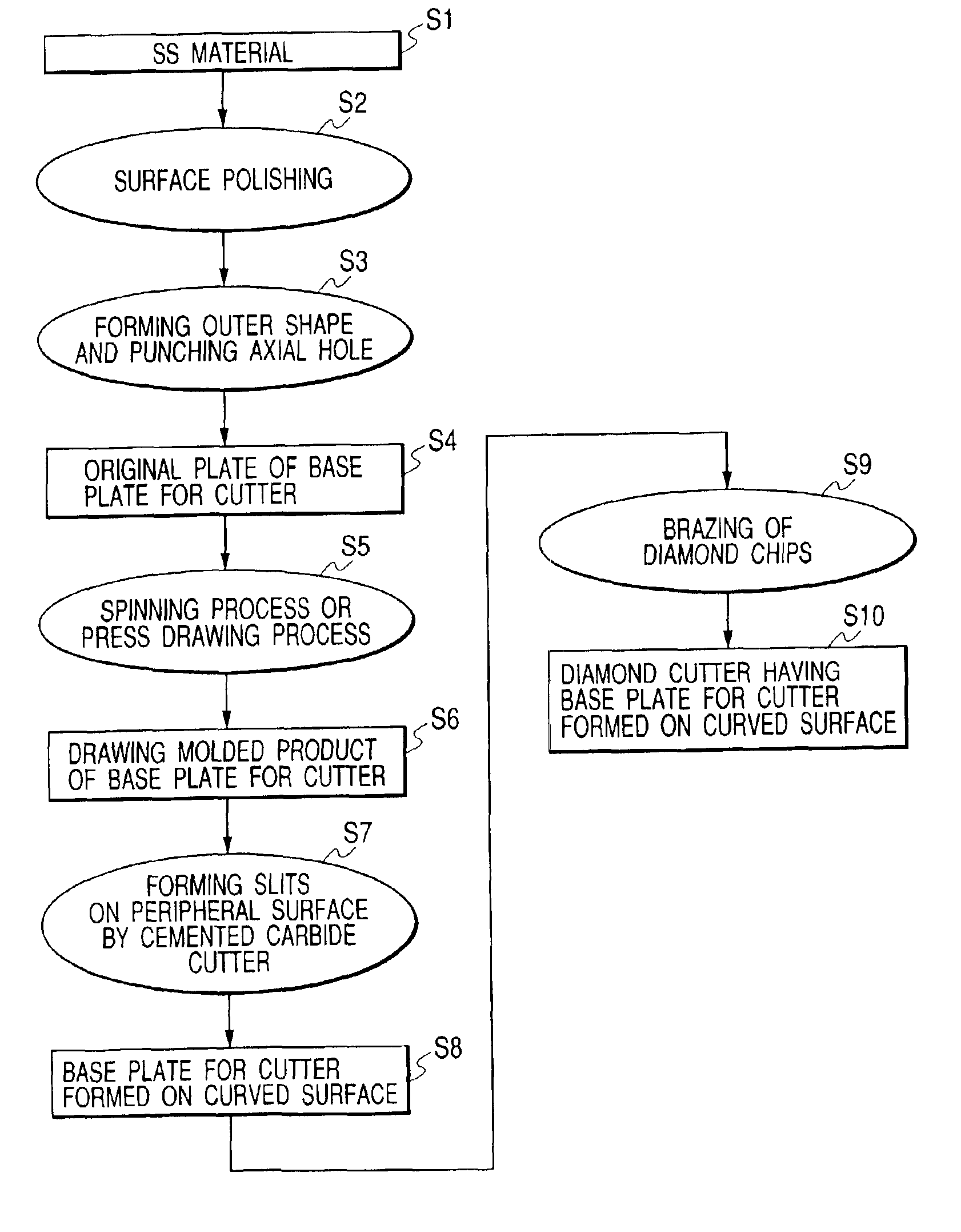
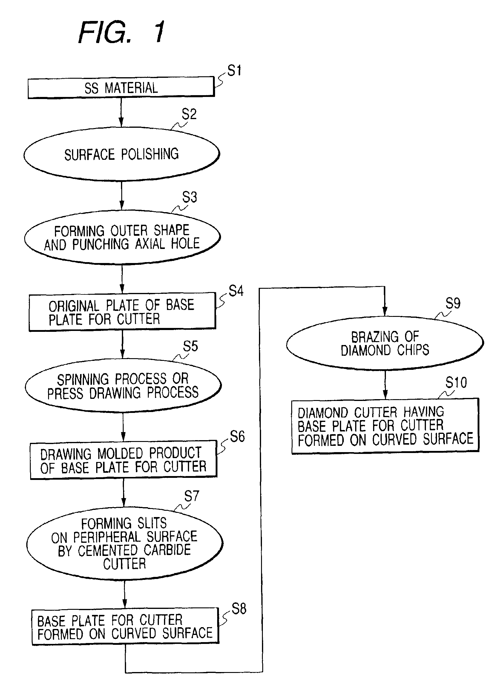
First, a description will be given of a manufacturing order of a diamond chip in accordance with the present invention with reference to FIG. 1. In a step S1, a steel sheet metal material is prepared. As the steel sheet metal material, a material having a low hardness is desirable, it is possible to employ any one of a rolled steel for a general structural purpose (SS material) standardized by Japanese Industrial Standards JIS-G3101, a cold rolled mild steel (SPC material) standardized by JIS-G3141 or a hot rolled mild steel (SPH material) standardized by JIS-G3181. Further, as a material to which a heat treatment thermal refining is not applied, it is possible to employ a cold rolled stainless steel (SUS material) standardized by JIS-G4305 or a hot rolled stainless steel (SUS material) standardized by JIS-G4304. Showing an example employin...


PUM


Abstract

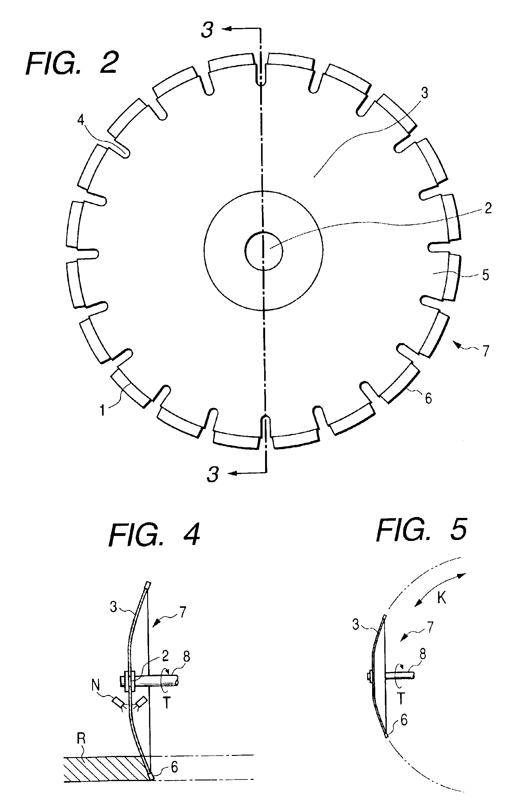
A diamond cutter 7 constituted by a cutter base plate 5 having a curved surface 3 by drawing molding a steel sheet metal material is provided. The cutter base plate 5 is obtained by preparing an original plate having an axial hole 2 and a circular outer shape from the steel sheet metal material, next spinning drawing or press molding, and forming the curved surface being 3 wholly point symmetrical about the axial hole 2 between the axial hole 2 and the outer shape 1.

Description

BACKGROUND OF THE INVENTIONThe present invention relates to a manufacturing method of a diamond cutter, and more particularly to an invention in which a cutter base plate constituting a diamond cutter is formed so as to have a curved surface.As is well known, cutting a road surface (asphalt) in a circular shape in order to form a manhole in a road, a hole for sticking up a pole or the like in a park, or the like is performed. For this purpose, a cutting apparatus in which a bit is mounted to a tip of a cylindrical casing has been conventionally used, however, since the equipment is large-scaled, a diamond cutter in which a diamond chip blade is mounted to an outer periphery of a circular cutter base plate has been gradually used. Paying attention to this diamond cutter, the circular flat diamond cutter has been conventionally manufactured by cutting a material having a comparatively high hardness in a circular shape by a laser beam cutting apparatus, applying a hardening and anneali...

Claims


Application Information

Patent Timeline
IPC IPC(8): B23D61/00B23D61/02B23D65/00B24D5/06B24D3/00B24D5/12
CPCB23D65/00B23D61/025
Inventor YABUKI, HIROYASUBANDO, KIYOSHISHIMIZU, MASAFUMI
Owner RIKEN DAIYAMONDO INDS
Learn More