Lateral spray nozzle

a spray nozzle and lateral technology, applied in the direction of burners, combustion types, combustion processes, etc., can solve the problems of high cost of boom mounted spraying systems, cumbersome pulling and manipulating of booms, and excessive liquid distribution in the overlap of spray patterns, so as to achieve uniform liquid distribution

Active Publication Date: 2005-03-15
SPRAYING SYST
View PDF8 Cites 10 Cited by
  • Summary
  • Abstract
  • Description
  • Claims
  • Application Information

AI Technical Summary

Benefits of technology

It is an object of the present invention to provide a spray nozzle which can be used in place of a plurality of boom mounted spray nozzles for producing a relatively wide flat spray curtain with substantially uniform liquid distribution.

Problems solved by technology

Excessive spacing between the spray nozzles can result in insufficient liquid distribution between adjacent discharging sprays, and too close of nozzle spacing can result in excessive liquid distribution in the overlapping spray patterns.
Because of the necessity for using a multiplicity of spray nozzles, boom mounted spraying systems are expensive.
Booms also can be cumbersome to pull and manipulate during spraying.
Additionally, many applications exist where boom spraying is impractical or ineffective.
For example, rugged terrain or other obstacles or impediments can restrict boom lengths.
This reduces the cost effectiveness of boom spraying in these applications.
If such obstacles or impediments are severe enough, manual spraying using handheld spray guns, which is both inaccurate and costly, could be required.
While proposals have been made for using a single spray nozzle to direct a relatively wide spray pattern in order to eliminate the necessity for a multiplicity of spray nozzles and the long supporting boom, such prior proposals have been relatively expensive and have not been effective for discharging sprays with uniform liquid distribution.

Method used


Image

  • Lateral spray nozzle
  • Lateral spray nozzle
  • Lateral spray nozzle

Examples


Embodiment Construction

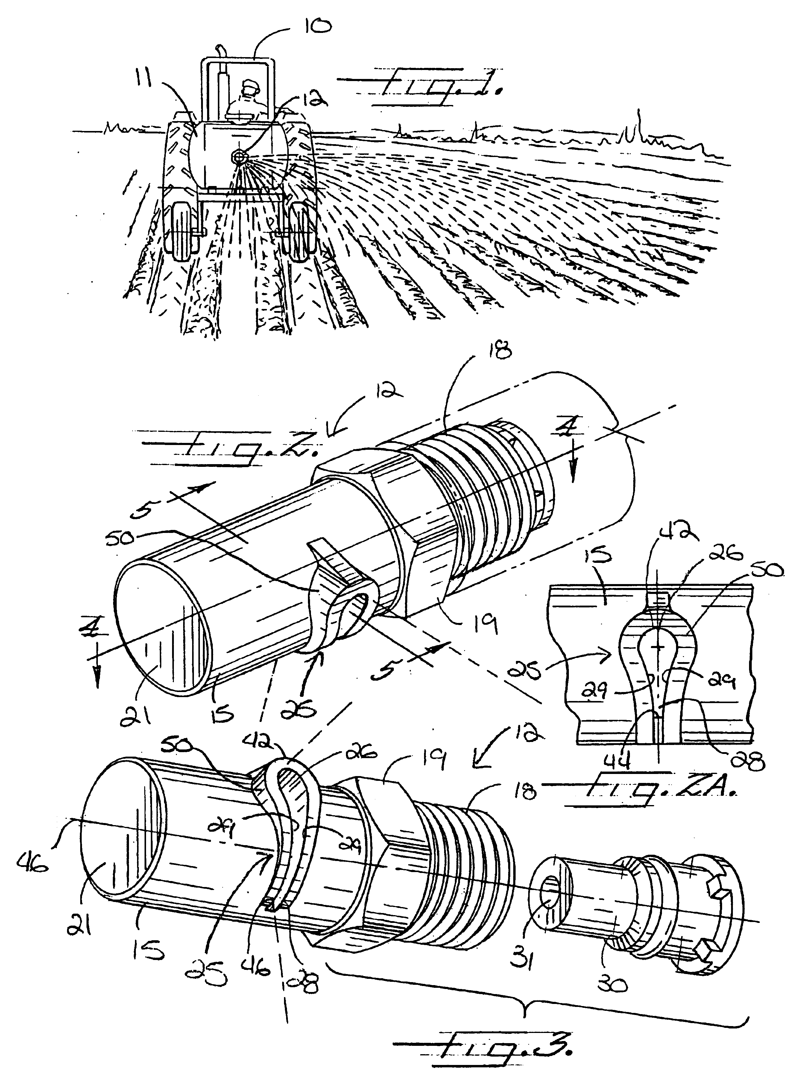
Referring now more particularly to FIG. 1 of the drawings, there is shown a vehicle 10 having a liquid spraying system that includes a liquid supply tank 11 and a spray nozzle 12 in accordance with the invention supported on a supply pipe connected to the tank in horizontal rearwardly extending relation to the tractor 10 for directing a spray behind and laterally to the side of the tractor 10. Such spray arrangement, for example, has utility in spraying chemicals for weed control along the side of a road. Alternatively, a pair of nozzles in accordance with the invention can be mounted in parallel relation, either side-by-side or one above the other, for directing discharging sprays in opposite lateral directions. It will be understood that the spray nozzle of the present invention eliminates the need for relatively expensive and cumbersome to manipulate spray booms commonly used in agricultural and roadside spraying, and allows spraying of areas that are impractical to spray with bo...


PUM


Abstract

A spray nozzle for directing a wide lateral spray curtain with substantially uniform liquid distribution throughout the length of the spray curtain is provided. The nozzle includes a nozzle body defining an elongated internal flow passage. The nozzle body includes an inlet end for connection to a pressurized liquid supply, a downstream end wall and a side wall. A discharge orifice is provided in the side wall of the nozzle body between the inlet end and the downstream end wall. The discharge orifice communicates with the internal flow passage of the nozzle body. The discharge orifice has a generally inverted teardrop configuration comprising a relatively larger area upper portion and a relatively smaller area lower portion arranged below the upper portion.

Description

FIELD OF THE INVENTIONThe present invention relates generally to liquid spray nozzles, and more particularly, to spray nozzle assemblies adapted for directing a flat spray pattern in a wide lateral direction.BACKGROUND OF THE INVENTIONIt is known to mount a plurality of spray nozzle assemblies along a liquid supply boom, up to twenty feet or more in length, which is pulled by a tractor or is part of a self-contained vehicle, with the discharging spray patterns of the nozzles in partially overlapping relation to each other to create a wide spray curtain. To achieve substantially uniform liquid distribution throughout the spray curtain, it is necessary that the spray nozzles be mounted on the spray boom at such intervals that the discharging sprays overlap in a determined fashion. Excessive spacing between the spray nozzles can result in insufficient liquid distribution between adjacent discharging sprays, and too close of nozzle spacing can result in excessive liquid distribution in ...

Claims


Application Information

Patent Timeline
Patent Type & Authority Patents(United States)
IPC IPC(8): A01C23/04A01C23/00B05B1/28B05B1/02B05B1/04
CPCA01C23/047B05B1/28B05B1/046
Inventor PAULSEN, GARYBOLMAN, BART R.MANEY, PATRICK M.
Owner SPRAYING SYST
Why Eureka
Try Eureka