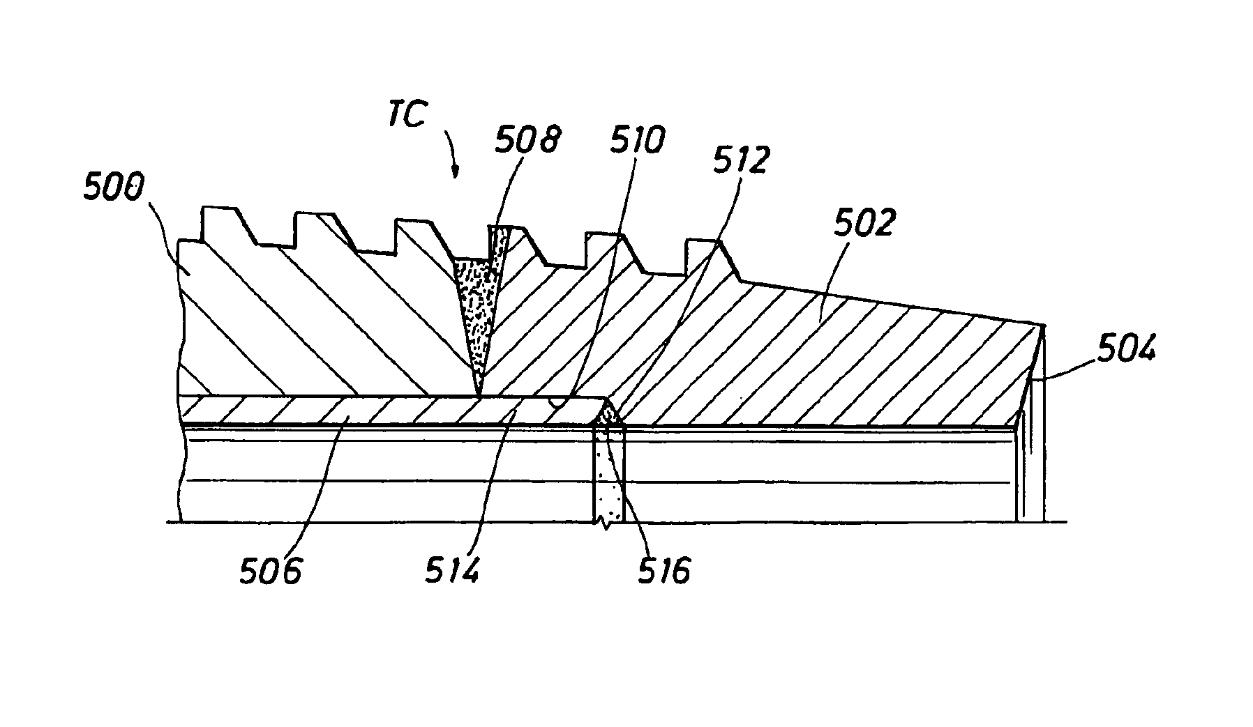
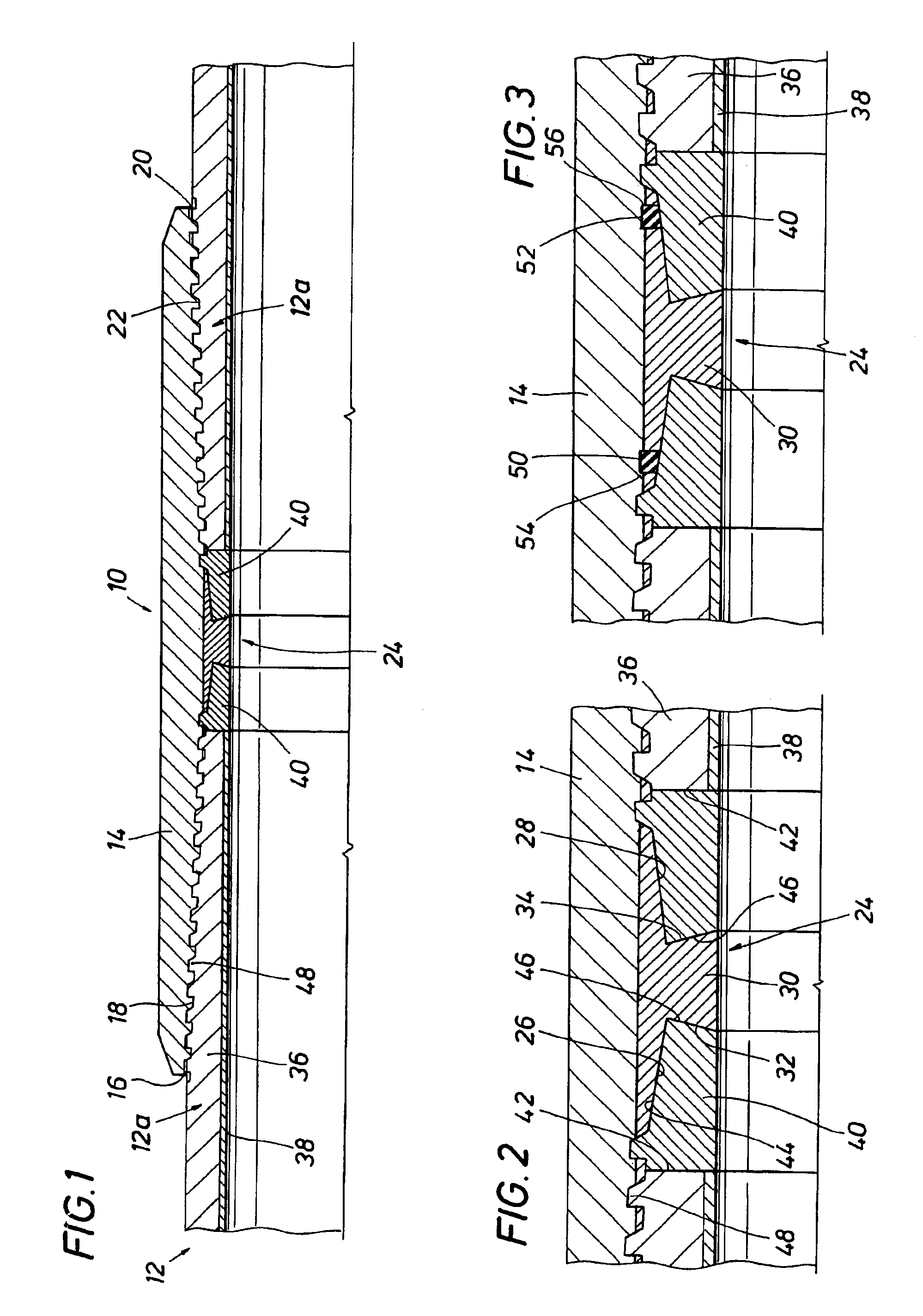
In one embodiment, the present invention provides a corrosion-resistant threaded connection assembly comprising a first tubular member having an outer tube of corrosion-prone material, e.g., carbon steel, and an inner tubular lining of corrosion-resistant material, e.g., stainless steel or some other corrosion-resistant metal alloy, the first tubular member including a first pin connection. The outer tube has a first end and a second end. The first pin connection comprises a nose portion formed on a first ring of corrosion-resistant material—e.g.—a metal alloy, secured to the first end of the outer tube of corrosion-prone material, thereby forming a first annular securing locus. The first ring of corrosion-resistant material defines a first annular, axially facing end surface and a first radially outwardly facing, annularly extending thread-free pin shoulder formed on the corrosion-resistant ring. A first axially extending, externally threaded portion providing male threads is formed at least partially on said outer tube and extends axially inwardly of the pin shoulder and first end surface, the first securing locus being disposed intermediate the first end surface and the end of the externally threaded portion distal the first end surface. The assembly further includes a second tubular member comprising a coupling having a first end and a second end, the coupling having a first box connection formed in the first end and a second box connection formed in the second end. The coupling further includes an internally disposed annularly extending section of corrosion-resistant material disposed intermediate the first and second ends of the coupling. Each of the box connections comprises a radially inwardly facing, annularly extending box shoulder formed on the section of corrosion-resistant material. Each of the box connections further includes an axially extending, internally threaded portion providing female threads complementary to the male threads of the first pin connection and extending axially outwardly of the thread-free box shoulder. The pin and box shoulders are sized and configured such that when respective ones of said first pin connections are threadedly received in the first and second box connections, the pin and box shoulders are in metal-to-metal sealing engagement.
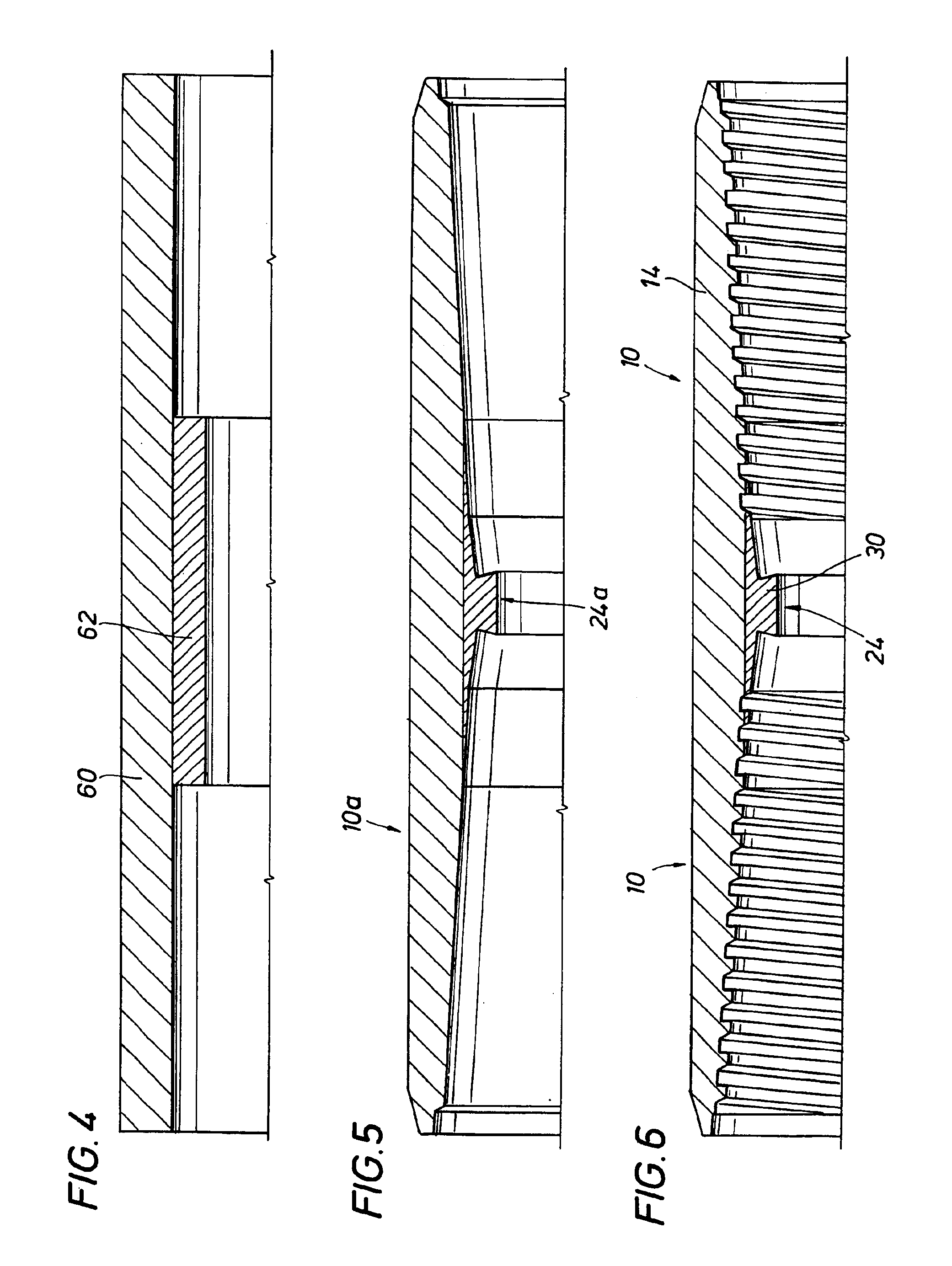
In yet another embodiment of the present invention, there is provided a workpiece for use in making a corrosion-resistant threaded tubular member. The workpiece includes an outer metal tube of corrosion-prone material having a first end, a second end, and an inner surface. A first ring of corrosion-resistant material is secured to the first end of the metal tube, a first annular securing locus being formed between the first ring and the first end of the metal tube. An inner metal tubular lining of corrosion-resistant material is disposed in the outer tube, the metal lining having a first end, a second end, and an outer surface, the outer surface of said lining overlying said inner surface of said tube and said first annular securing locus, the first end of said lining being secured to the first ring.
In yet another embodiment of the present invention, there is provided a method of forming a workpiece for use in making a corrosion-resistant threaded tubular member. In the method, a metal tube of corrosion-prone material is provided, the metal tube having a first end and a second end. A first ring of corrosion-resistant material is permanently secured or bonded to the first end of the metal tube to form a first annular securing locus between the first ring and the first end of the metal tube. The method further includes providing a metal tubular liner of corrosion-resistant material, the liner having a first end and a second end and disposing the liner in the tube, the liner overlying the first annular securing locus and being secured to the first ring.
Yet a further embodiment of the present invention comprises a corrosion-resistant, externally threaded tubular member. The externally threaded tubular member includes an outer metal tube of corrosion-prone material having a first end, a second end, and an inner surface. A first ring of corrosion-resistant material is secured to the first end of the metal tube. A first annular securing locus is formed between the first ring and the first end of the metal tube. An inner, metal tubular lining of corrosion-resistant material is disposed in the outer tube, the metal lining having a first end, a second end, and an outer surface. The outer surface of the lining overlies the inner surface of the outer metal tube and the first annular securing locus, the first end of the lining being secured to the first ring. The first ring defines an annular, axially facing end surface and can have a first radially outwardly facing, annularly extending threadfree pin shoulder formed externally on the first ring. A first axially extending, externally threaded portion providing male threads is formed at least partially on the tube and extends axially inwardly of the first end surface. The first securing locus is disposed intermediate the first end surface and the end of the first externally threaded portion distal the first end surface.
In still another embodiment of the present invention, there is provided a method of forming a corrosion-resistant, externally threaded tubular member. In the method, a metal tube of corrosion-prone material is provided, the metal tube having a first end and a second end. The method furthers includes securing a first ring of corrosion-resistant material to the first end of the metal tube by permanently bonding the first ring to the first end of the metal tube to form a first annular securing locus between the first ring and the first end of the metal tube, the first ring facing a first end surface. The method further includes providing a metal tubular liner of corrosion-resistant material, the liner having a first end and a second end, and disposing the liner in the tube, the liner overlying the first annular securing locus and being secured to the first ring. The method further includes forming a first axially extending, externally threaded portion providing male threads, the first threaded portion extending axially inwardly of the first end surface and being at least partially formed on the metal tube, the first securing locus being disposed intermediate the first end surface and the end of said first externally threaded portion distal said first end surface, and optionally forming a first radially outwardly facing, annularly extending, threadfree shoulder on the first ring.


