
Adaptive auxiliary condensing device and method

a technology of auxiliary condensers and condensers, which is applied in the field of refrigeration systems, can solve the problems of consuming more energy, reducing the cooling capacity of the evaporator, and shortening the life of the compressor, so as to achieve safe refrigeration temperatures, convenient installation, and maintain safe refrigeration temperatures

Inactive Publication Date: 2005-03-08
MILES SHARON LOUISE +1
View PDF30 Cites 34 Cited by
  • Summary
  • Abstract
  • Description
  • Claims
  • Application Information

AI Technical Summary

Benefits of technology

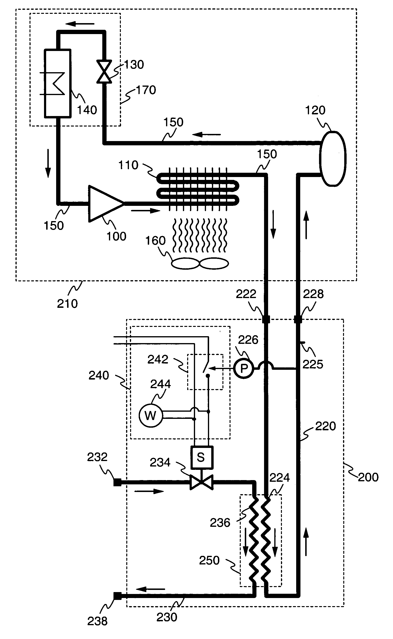
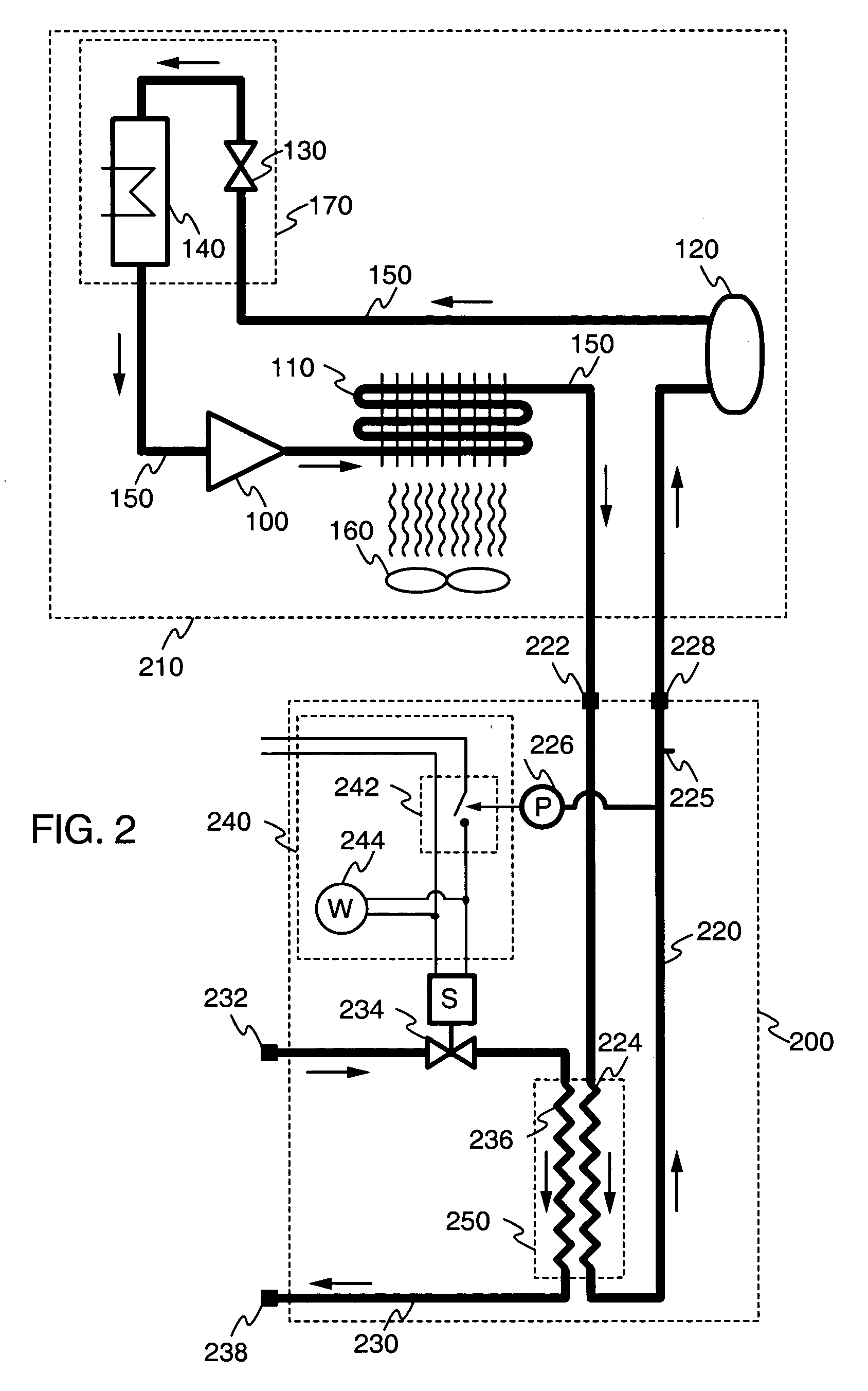
It is an object of the present invention to solve various problems associated with air-cooled refrigeration appliances. In one aspect of the invention, an adaptive water-cooled auxiliary condenser device is provided that can be attached to an existing refrigeration appliance. The device is self-contained, inexpensive, and easily connected. Once attached, the device provides automatic, on-demand water cooling. The device has a refrigerant fluid line, a water line, and an electrical circuit. The refrigerant fluid line has a refrigerant fluid inlet, a refrigerant fluid heat exchange section, a refrigerant fluid state sensor, and a refrigerant fluid outlet. The water line has a water inlet, a controllable water flow valve, a water heat exchange section, and a water outlet. The water heat exchange section and the refrigerant fluid heat exchange section are in heat exchange relationship. The electrical circuit is connected to the refrigerant fluid state sensor and the controllable water flow valve such that the water flow valve is opened when a sensed refrigerant fluid state rises above a first predetermined threshold value and the water flow valve is closed when the sensed refrigerant fluid state falls below a second predetermined threshold value. The electrical circuit may also include a warning indicator such as a light or sound alarm.
The self-contained device is preferably housed in a metal box that may be easily installed by connecting its water inlet and outlet to a locally available water source and drain, respectively, connecting its refrigerant fluid inlet and outlet to the high-pressure line of a refrigeration appliance so that the device is just downstream from the appliance's air-cooled condenser, and connecting the electrical circuit to a power supply.
Because the water flow turns on only when needed (i.e., when the air-cooled condenser efficiency drops below normal) the device does not use electric power or water under normal operating conditions. The refrigerant simply flows transparently through the device. If needed, however, the flow of water provides additional cooling that maintains safe refrigeration temperatures in the appliance. In this case, the warning indicator provides an alert that the appliance should be serviced. However, servicing is not critical since the back-up water cooling will maintain safe refrigeration temperatures. The device therefore provides a back-up which may be installed to repair, prevent or safeguard against failures in air-cooled refrigeration appliances. The device is inexpensive and may be easily installed by a service technician.

Problems solved by technology

If heat is not efficiently dissipated at the condenser, however, the cooling capacity of the evaporator will be reduced.
This will cause the compressor to turn on more frequently and / or run for longer periods of time, shortening the life of the compressor and consuming more energy.
Inefficient heat transfer at the condenser can thus increase the probability of compressor failure.
Moreover, if the heat transfer efficiency at the condenser drops below a critical level, the evaporator will no longer be able to absorb enough heat to maintain the required refrigeration temperature, even if the compressor runs continuously.
Unfortunately, common refrigeration appliances often experience a significant degradation in condenser efficiency.
Another common cause of condenser inefficiency is an obstruction of the airflow, e.g., by a plastic bag covering the condenser or blocking the air intake.
If the fan fails, this will obviously reduce the airflow and condenser efficiency as well.
To make matters worse, several of these factors may be present at once, compounding the problem.
Replacing or repairing the appliance, however, can be expensive and time-consuming.
These systems, however, require a continuous flow of water to dissipate the heat from the condenser.
This use of water increases the operating costs of the appliance and, in some circumstances, is not feasible when the water supply is limited (e.g., when water is available only from a well).
Because of these disadvantages, water-cooled refrigeration appliances are often not affordable or practical, forcing people to continue to use common air-cooled refrigeration appliances.

Method used


Image

  • Adaptive auxiliary condensing device and method
  • Adaptive auxiliary condensing device and method
  • Adaptive auxiliary condensing device and method

Examples


Embodiment Construction

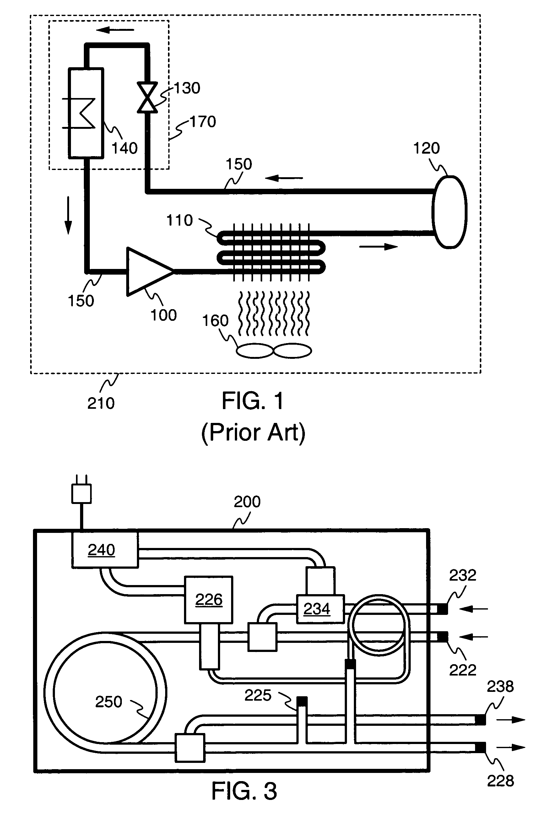
Particular embodiments of the present invention will now be described in detail with reference to the drawing figures. The purpose and function of the present invention is best understood by first reviewing the structure and operation of a conventional air-cooled refrigeration system, as illustrated in FIG. 1. The system includes the following components connected in series to form a closed cycle: a compressor 100, air-cooled condenser 110, receiver 120, expansion valve130, and evaporator 140. These components are connected by a refrigerant fluid line 150. Optionally, a fan 160 may be associated with air-cooled condenser 110. The system may be understood as being divided by the compressor 100 and expansion valve 130 into a high-pressure portion and a low-pressure portion. The high-pressure portion includes the condenser 110 and receiver 120, while the low-pressure portion includes the evaporator 140.

In operation, a gaseous refrigerant fluid enters the compressor 100 which increase...


PUM


Abstract

A water-cooled auxiliary condenser device 200 receives refrigerant from an external refrigeration system 210 just downstream from its air-cooled condenser 110. The refrigerant passes through a water-cooled condenser 250, and the refrigerant state is sensed by a temperature or pressure sensor 226. If the sensed state of the refrigerant rises above a first threshold, the flow of water through the water-cooled condenser 250 is increased, e.g., turned ON, using a controllable water valve 234. When the sensed state of the refrigerant drops below a second threshold, the water flow through the water-cooled condenser 250 is decreased, e.g., turned OFF. The refrigerant returns to the refrigeration system just upstream from its liquid receiver 120. In the event that air-cooled condenser 110 fails, device 200 automatically activates the water-cooled condenser 250 to maintain safe refrigeration temperatures in the appliance. When not required, device 200 remains passive and does not use any water or electric.

Description

FIELD OF THE INVENTION This invention relates generally to refrigeration systems. More specifically, it relates to air-cooled refrigeration systems and auxiliary water-cooled condensers for use with such systems. BACKGROUND OF THE INVENTION Common residential and commercial refrigeration appliances rely on air-cooled condensers as part of the refrigeration cycle. In a conventional refrigeration system of this type, the condenser dissipates heat from the warm, high-pressure refrigerant fluid into the ambient air. Often a fan promotes this dissipative heat transfer by creating a flow of air over the surface of the condenser. In normal operation, sufficient heat is dissipated by the condenser in the high-pressure portion of the cycle so that when the fluid passes through the evaporator in the low-pressure portion of the cycle, its temperature is low enough to produce the required cooling. In many systems the compressor turns on intermittently, cycling the fluid and producing cooling o...

Claims


Application Information

Patent Timeline
Patent Type & Authority Patents(United States)
IPC IPC(8): F25B6/00F25B6/04
CPCF25B6/04F25B2700/21163F25B2500/06F25B2339/047
Inventor MILES, DONALD R.
Owner MILES SHARON LOUISE
Learn More