
Attenuating fluid manifold for meltblowing die

a technology of attenuating fluid and melt blowing die, which is applied in the field of attenuating fluid manifold for melt blowing die, can solve the problems that the porousness may not always provide a sufficient basis for evaluating the quality or uniformity of nonwoven web, and the web may still exhibit non-uniform performance characteristics, so as to achieve uniform physical properties and high quality.

Inactive Publication Date: 2005-03-01
3M INNOVATIVE PROPERTIES CO
View PDF27 Cites 69 Cited by
  • Summary
  • Abstract
  • Description
  • Claims
  • Application Information

AI Technical Summary

Benefits of technology

Although useful, macroscopic nonwoven web properties such as basis weight, average fiber diameter, web thickness or porosity may not always provide a sufficient basis for evaluating nonwoven web quality or uniformity. These macroscopic web properties typically are determined by cutting small swatches from various portions of the web or by using sensors to monitor portions of a moving web. These approaches can be susceptible to sampling and measurement errors that may skew the results, especially if used to evaluate low basis weight or highly porous webs. In addition, although a nonwoven web may exhibit uniform measured basis weight, fiber diameter, web thickness or porosity, the web may nonetheless exhibit nonuniform performance characteristics due to differences in attenuation of the individual web fibers. A more uniform web could be obtained if each extruded filament was subjected to identical or substantially identical streams of attenuating fluid. Ideally, the attenuating fluid streams would impinge upon the filaments at an identical volumetric flow rate and temperature along the width of the die. After attenuation and collection, the resulting attenuated fibers may have more uniform physical properties from fiber to fiber and may form higher quality or more uniform melt blown nonwoven webs.
The desired fiber physical property uniformity preferably is evaluated by determining one or more intrinsic physical or chemical properties of the collected fibers, e.g., their weight average or number average molecular weight, and more preferably their molecular weight distribution. Molecular weight distribution can conveniently be characterized in terms of polydispersity. By measuring properties of fibers rather than of web swatches, sampling errors are reduced and a more accurate measurement of web quality or uniformity can be obtained.
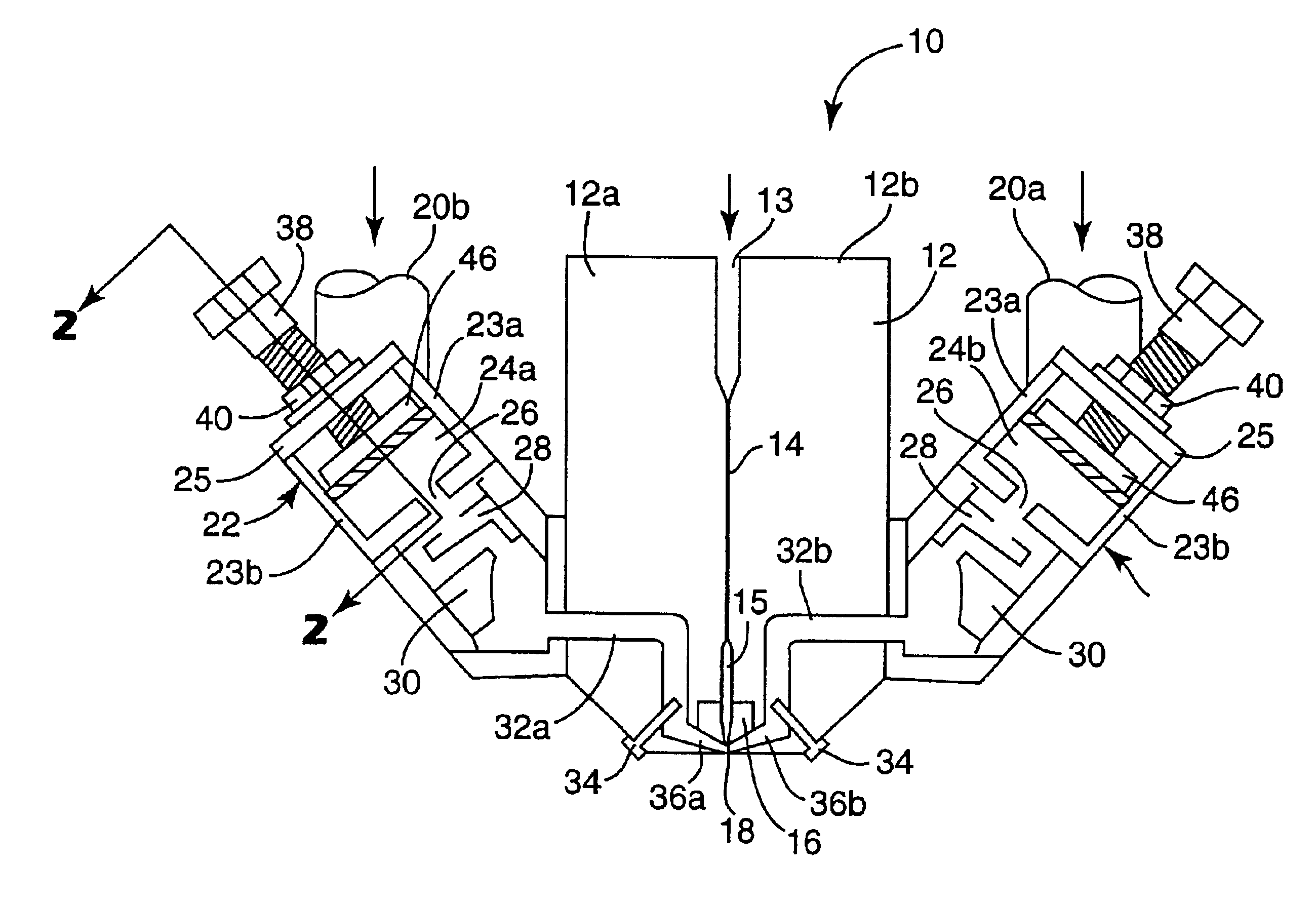
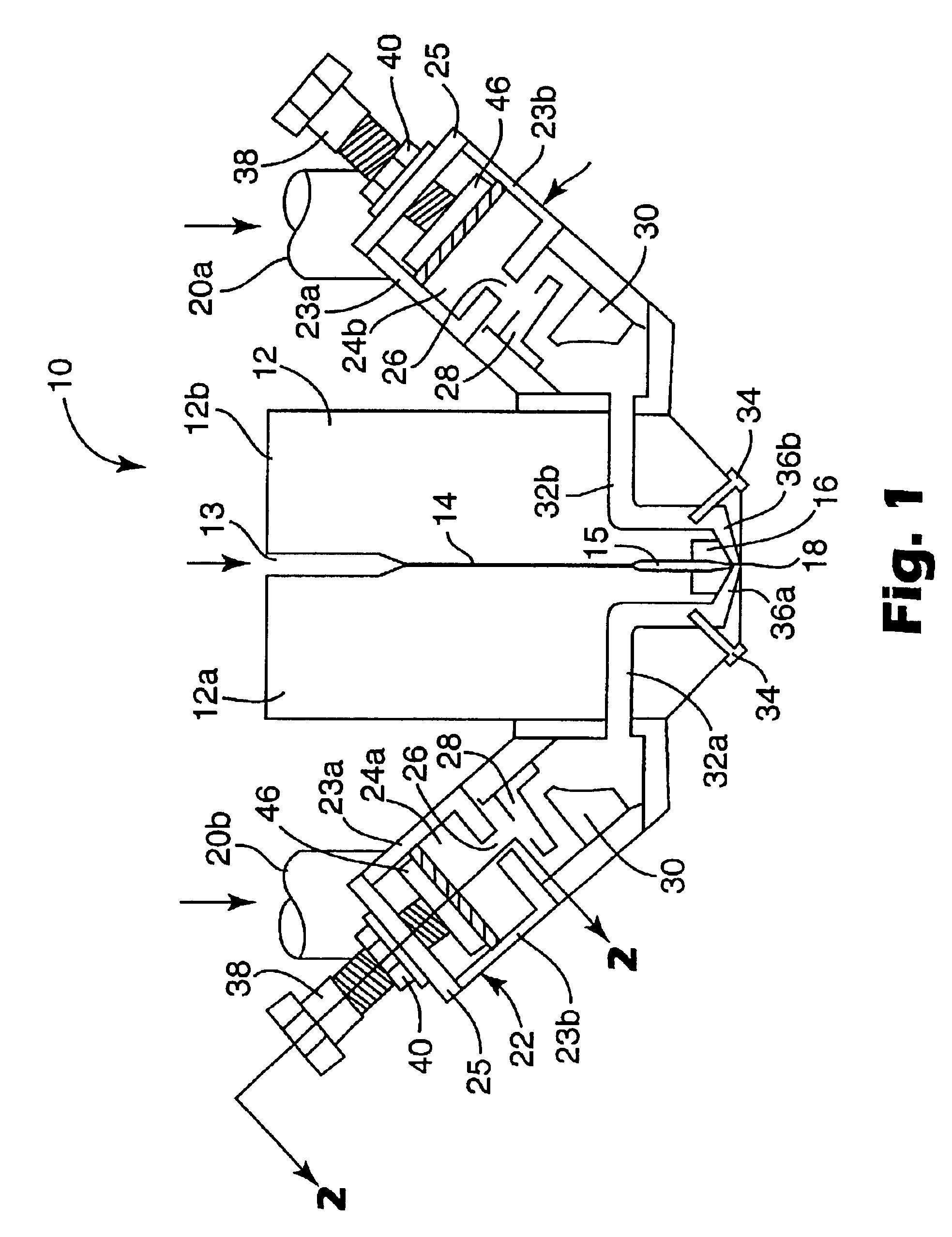
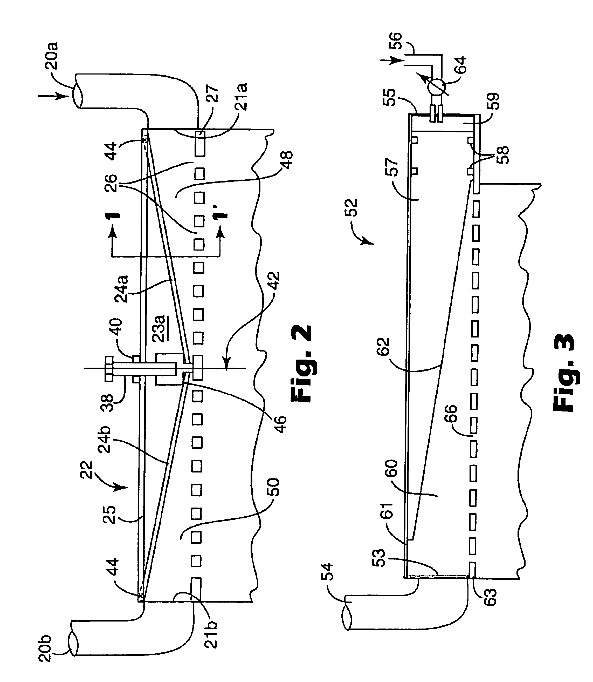
The present invention provides, in one aspect, a meltblowing apparatus comprising:a) a meltblowing die having (i) a plurality of filament outlets and (ii) a plurality of attenuating fluid flow channels in fluid communication with a plurality of attenuating fluid outlets exiting the die near the filament outlets;b) a manifold in fluid communication with a plurality of the channels, the manifold having at least one inlet for attenuating fluid; andc) an attenuating fluid distribution passage between a manifold inlet and corresponding attenuating fluid outlets, wherein the distribution characteristics of the passage can be changed while the die and manifold are assembled in order to make the attenuating fluid temperature in the channels more uniform.
The devices and methods of the invention can provide higher quality or more uniform melt blown nonwoven webs, including webs having more uniform physical properties from fiber to fiber. The devices and methods of the invention can be adjusted to provide uniform delivery of attenuating fluid to a meltblowing die over a variety of attenuating fluid flow rates and meltblowing die operating conditions. Preferred embodiments of the invention permit adjustment during meltblowing.

Problems solved by technology

Although useful, macroscopic nonwoven web properties such as basis weight, average fiber diameter, web thickness or porosity may not always provide a sufficient basis for evaluating nonwoven web quality or uniformity.
These approaches can be susceptible to sampling and measurement errors that may skew the results, especially if used to evaluate low basis weight or highly porous webs.
In addition, although a nonwoven web may exhibit uniform measured basis weight, fiber diameter, web thickness or porosity, the web may nonetheless exhibit nonuniform performance characteristics due to differences in attenuation of the individual web fibers.

Method used


Image

  • Attenuating fluid manifold for meltblowing die
  • Attenuating fluid manifold for meltblowing die
  • Attenuating fluid manifold for meltblowing die

Examples


Embodiment Construction

As used in this specification, the phrase “nonwoven web” refers to a fibrous web characterized by entanglement, and preferably having sufficient coherency and strength to be self-supporting.

The term “meltblowing” means a method for forming a nonwoven web by extruding a fiber-forming material through a plurality of orifices to form filaments while contacting the filaments with air or other fluid to attenuate the filaments into fibers and thereafter collecting a layer of the attenuated fibers.

The phrase “meltblowing temperatures” refers to the meltblowing die temperatures at which meltblowing typically is performed. Depending on the application, meltblowing temperatures can be as high as 315° C., 325° C. or even 340° C. or more.

The phrase “meltblowing die” refers to a die for use in meltblowing.

The term “passage” refers to an enclosed space in a meltblowing die or attenuating fluid manifold through which attenuating fluid flow can occur.

The phrase “distribution passage” refers to a pa...


PUM

PropertyMeasurementUnit
Temperatureaaaaaaaaaa
Lengthaaaaaaaaaa
Temperatureaaaaaaaaaa

Abstract

Melt blown nonwoven webs are formed by supplying attenuating fluid to a meltblowing die through an attenuating fluid distribution passage whose distribution characteristics can be changed while the die and manifold are assembled. By adjusting the distribution characteristics of the passage, the mass flow rate of attenuating fluid to channels in the meltblowing die and the temperature of the attenuating fluid at the die outlets can be made more uniform.

Description

FIELD OF THE INVENTIONThis invention relates to devices and methods for preparing melt blown fibers.BACKGROUNDNonwoven webs typically are formed using a meltblowing process in which filaments are extruded from a series of small orifices while being attenuated into fibers using hot air or other attenuating fluid. The attenuated fibers are formed into a web on a remotely-located collector or other suitable surface.There has been an ongoing effort to improve the uniformity of nonwoven webs. Web uniformity typically is evaluated based on factors such as basis weight, average fiber diameter, web thickness or porosity. Process variables such as material throughput, air flow rate, die to collector distance, and the like can be altered or controlled to improve nonwoven web uniformity. In addition, changes can be made in the design of the meltblowing apparatus. References describing such measures include U.S. Pat. Nos. 4,889,476, 5,236,641, 5,248,247, 5,260,003, 5,582,907, 5,728,407, 5,891,4...

Claims


Application Information

Patent Timeline
IPC IPC(8): D01D4/02D01D5/08D01D4/00D01D5/098D04H3/16
CPCD01D4/025D01D1/09D01D5/0985D01D4/02D01D5/098
Inventor ERICKSON, STANLEY C.BREISTER, JAMES C.
Owner 3M INNOVATIVE PROPERTIES CO
Learn More