
Liquid hydrocarbon treatment method

a liquid hydrocarbon and treatment method technology, applied in the field of liquid hydrocarbon treatment methods, can solve the problems of small discontinuous regions, adversely affecting the subsequent hydrocarbon separation step, undetected entrapment, etc., and achieve the effect of reducing the concentration of mercaptan

Inactive Publication Date: 2005-03-01
EXXON RES & ENG CO +1
View PDF29 Cites 12 Cited by
  • Summary
  • Abstract
  • Description
  • Claims
  • Application Information

AI Technical Summary

Benefits of technology

The invention relates to methods for treating and upgrading hydrocarbons containing acidic species such as mercaptans, particularly mercaptans having a molecular weight higher than about C4. The methods involve contacting the hydrocarbon with a treatment composition containing water, alkali metal hydroxide, cobalt phthalocyanine sulfonate, and alkylphenols, and then separating an upgraded hydrocarbon with reduced mercaptan concentration. The methods can be carried out using an extractant composition containing water, alkali metal hydroxide, cobalt phthalocyanine sulfonate, and alkylphenols, where the extractant is substantially immiscible with its analogous aqueous alkali metal hydroxide and contains water, dissolved alkali metal alkylphenylate, dissolved alkali metal hydroxide, and dissolved sulfonated cobalt phthalocyanine. The technical effects of the invention include improved quality and yield of upgraded hydrocarbons containing reduced amounts of acidic species.

Problems solved by technology

Such intimate contacting often results in the formation of small discontinuous regions (also referred to as “dispersion”) of treatment solution in the hydrocarbon.
While the small aqueous regions provide sufficient surface area for efficient mercaptan transfer, they adversely affect the subsequent hydrocarbon separation step and may be undesirably entrained in the treated hydrocarbon.
Even so, the formation of discontinuous regions of aqueous treatment solution is not eliminated, particularly in continuous process.
Undesirable aqueous phase entrainment is also present in this method, and is made worse when employing higher viscosity treatment solutions containing higher alkali metal hydroxide concentration.

Method used


Image

  • Liquid hydrocarbon treatment method
  • Liquid hydrocarbon treatment method
  • Liquid hydrocarbon treatment method

Examples


example 1

Impact of Sulfonated Cobalt Pthalocyanine on Droplet Size Distribution

A LASENTECH™ (Laser Sensor Technology, Inc., Redmond, Wash. USA), Focused Laser Beam Reflecatance Measuring Device (FBRM®) was used to monitor the size of dispersed aqueous potassium cresylate droplets in a continuous naphtha phase. The instrument measures the back-reflectance from a rapidly spinning laser beam to determine the distribution of “chord lengths” for particles that pass through the point of focus of the beam. In the case of spherical particles, the chord length is directly proportional to particle diameter. The data is collected as the number of counts per second sorted by chord length in one thousand linear size bins. Several hundred thousand chord lengths are typically measured per second to provide a statistically significant measure of chord length size distribution. This methodology is especially suited to detecting changes in this distribution as a function of changing process variables.

In this ...

example 2

Determination of Extraction Coefficients for Selectively Hydrotreated Naphtha

Determination of mercaptan extraction coefficient, Keq, was conducted as follows. About 50 m is of selectively hydrotreated naphtha was poured into a 250 ml Schlenck flask to which had been added a Teflon-coated stir bar. This flask was attached to an inert gas / vacuum manifold by rubber tubing. The naphtha was degassed by repeated evacuation / nitrogen refill cycles (20 times). Oxygen was removed during these experiments to prevent reacting the extracted mercaptide anions with oxygen, which would produce naphtha-soluble disulfides. Due to the relatively high volatility of naphtha at room temperature, two ten mls sample of the degassed naphtha were removed by syringe at this point to obtain total sulfur in the feed following degassing. Typically the sulfur content was increased by 2-7-wppm sulfur due to evaporative losses. Following degassing, the naphtha was placed in a temperature-controlled oil bath and equ...

example 3

Extraction Coefficients Determined At Constant Cresol Weight %

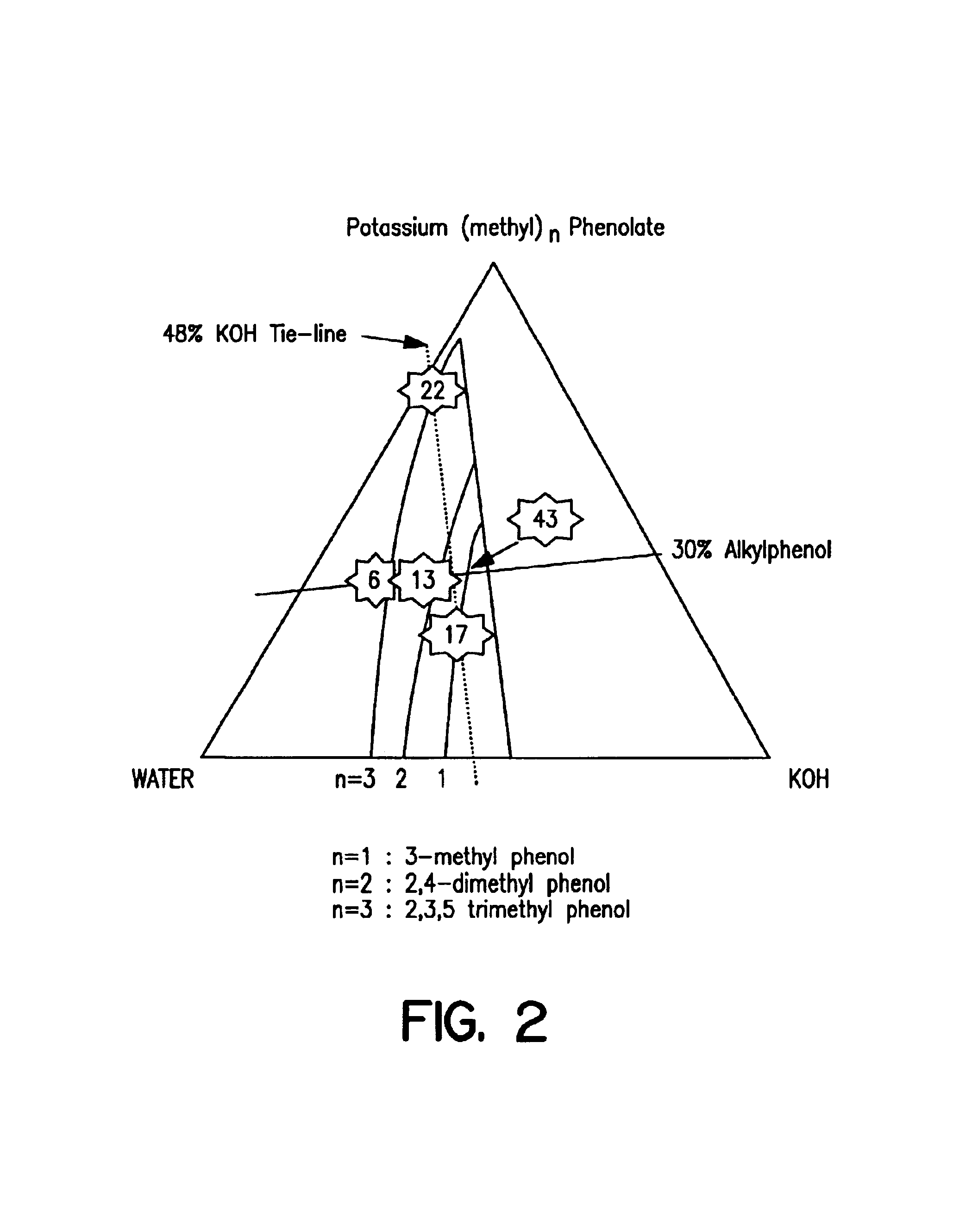
As is illustrated in FIG. 2 the area of the two-phase region in the phase diagram increases with alkylphenol molecular weight. These phase diagrams were determined experimentally by standard, conventional methods. The phase boundary line shifts as a function of molecular weight and also determines the composition of the extractant phase within the two-phase region. In order to compare the extractive power of two-phase extractants prepared from different molecular weight alkylphenols, extractants were prepared having a constant alkylphenol content in the top layer of about 30 wt. %. Accordingly, starting composition were selected for each of three different molecular weight alkylphenols to achieve this concentration in the extractant phase. On this basis, 3-methylphenol, 2,4-dimethylphenol and 2,3,5-trimethylphenol were compared and the results are depicted in FIG. 2.

The figure shows the phase boundary for each of the alky...


PUM

PropertyMeasurementUnit
pressureaaaaaaaaaa
temperatureaaaaaaaaaa
viscosityaaaaaaaaaa

Abstract

The invention relates to a method for treating and upgrading a hydrocarbon containing acidic species such as mercaptans, comprising:(a) contacting the hydrocarbon, in the essential absence of oxygen, with a first phase of a treatment composition containing water, dissolved alkali metal hydroxide, cobalt phthalocyanine sulfonate, and dissolved alkylphenylates and having at least two phases, (i) the first phase containing water, alkali metal alkylphenylate, dissolved alkali metal hydroxide, and dissolved sulfonated cobalt phthalocyanine, and (ii) the second phase containing water and dissolved alkali metal hydroxide; and then (b) separating an upgraded hydrocarbon.

Description

FIELD OF THE INVENTIONThe invention relates to a method for treating liquid hydrocarbons in order to remove acidic impurities, such as mercaptans, particularly mercaptans having a molecular weight of about C4 (C4H10S=90 g / mole) and higher, such as recombinant mercaptans.BACKGROUND OF THE INVENTIONUndesirable acidic species such as mercaptans may be removed from liquid hydrocarbons with conventional aqueous treatment methods. In one conventional method, the hydrocarbon contacts an aqueous treatment solution containing an alkali metal hydroxide. The hydrocarbon contacts the treatment solution, and mercaptans are extracted from the hydrocarbon to the treatment solution where they form mercaptide species. The hydrocarbon and the treatment solution are then separated, and a treated hydrocarbon is conducted away from the process. Intimate contacting between the hydrocarbon and aqueous phase leads to more efficient transfer of the mercaptans from the hydrocarbon to the aqueous phase, parti...

Claims


Application Information

Patent Timeline
Patent Type & Authority Patents(United States)
IPC IPC(8): C10G67/10C10G67/00C10G67/04C10G19/08C10G21/28C10G19/00C10G21/00C10G19/02B01D11/04C10G19/04C10G21/06C10G21/08C10G27/06C10G27/10C10G45/02C10G53/04C10G53/12C10G53/14C10G67/12
CPCC10G19/02C10G19/04C10G19/08C10G21/06C10G21/08C10G21/28C10G67/04C10G67/10C10G67/12C10G45/02C10G2300/202C10G2400/02C10G2300/1044
Inventor GREANEY, MARK A.LE, BIHN N.LETA, DANIEL P.BEGASSE, JOHN N.HUANG, CHARLES T.TURNER, VERLIN KEITH
Owner EXXON RES & ENG CO
Learn More