
System and method for providing multimedia jitter buffer adjustment for packet-switched networks

Inactive Publication Date: 2005-02-22
CISCO TECH INC
View PDF13 Cites 271 Cited by
  • Summary
  • Abstract
  • Description
  • Claims
  • Application Information

AI Technical Summary

Benefits of technology

The present invention provides advantages of dynamically adjusting the buffer depth depending on the network conditions. Further, the adjustments to the buffer depth maintain the delicate balance between the need to eliminate jitter and the need to reduce latency.

Problems solved by technology

However, the advantages of reduced cost and bandwidth savings by using voice-over-packet networks are associated with quality-of-service (QoS) problems, such as latency, packet loss, and jitter.
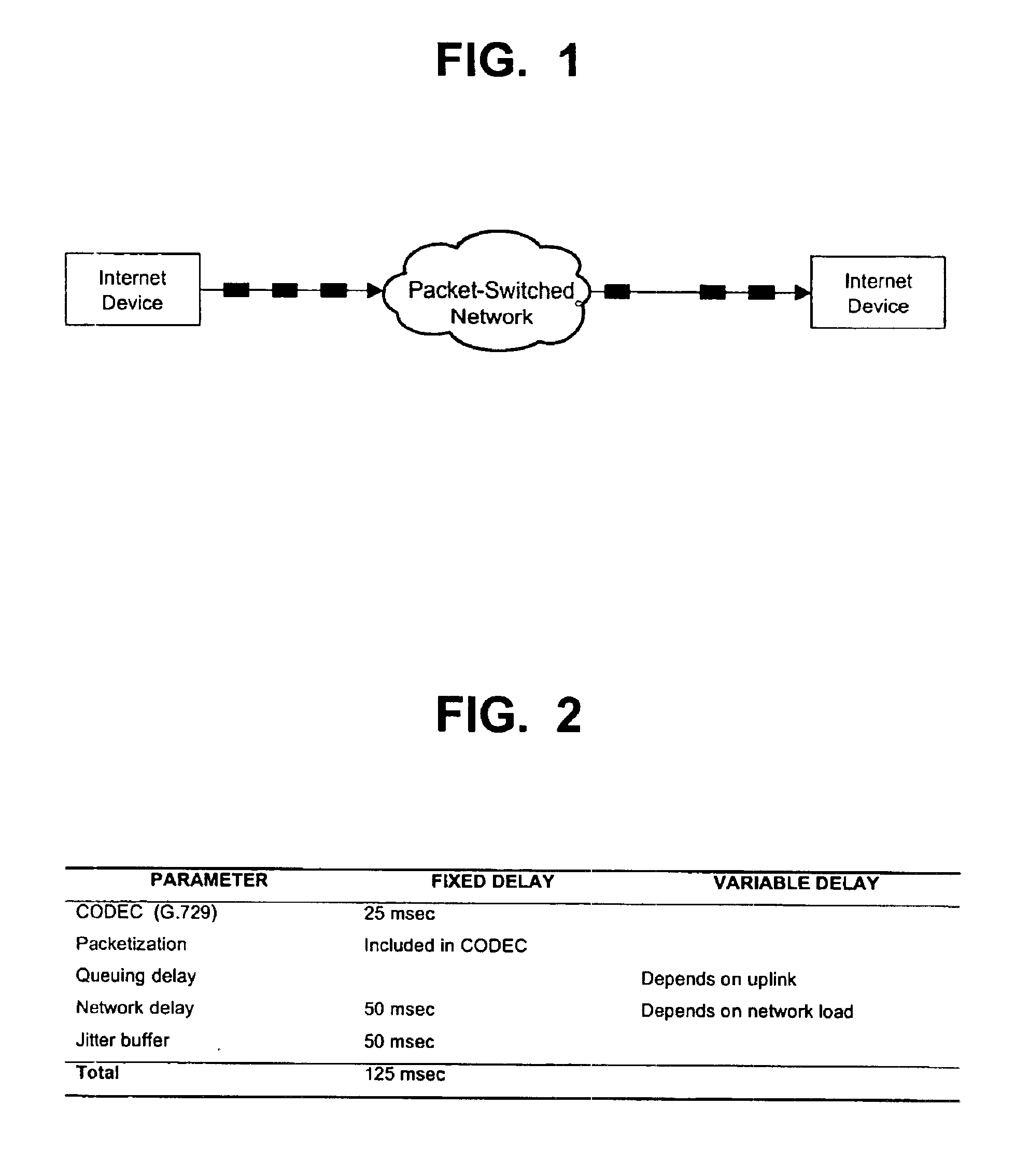
Further, the data stream is not uniform—data packets carrying the voice conversation can arrive at the destination at irregular intervals, as shown in FIG.
This causes a short silent period that makes the voice sound choppy or garbled.
Such discontinuity degrades the audio quality and decreases the desirability of using the Internet to conduct voice communications.
However, every frame buffered adds latency, or delay, which is especially relevant to voice calls.
When added to the latency of the Internet itself, this can rapidly become unacceptable.
Given that many Internet locations are 100 msec or more (one way) apart, adding 50 msec of jitter buffer latency accounts for a significant fraction of the acceptable delay.
A delicate balance lies between the need to eliminate jitter and the need to reduce latency.
Accordingly, when network traffic is low, the jitter buffer may be too large, thereby introducing unnecessary latency.
However, when network load is high, the jitter buffer may be too small such that network perturbations, for example, packet loss and jitter, will cause audible distortion on the voice conversation.
In addition, for Internet devices having a fixed jitter buffer depth, when the jitter buffer is too large, the unused memory resources in the system are not available to perform other functions.

Method used


Image

  • System and method for providing multimedia jitter buffer adjustment for packet-switched networks
  • System and method for providing multimedia jitter buffer adjustment for packet-switched networks
  • System and method for providing multimedia jitter buffer adjustment for packet-switched networks

Examples


Embodiment Construction

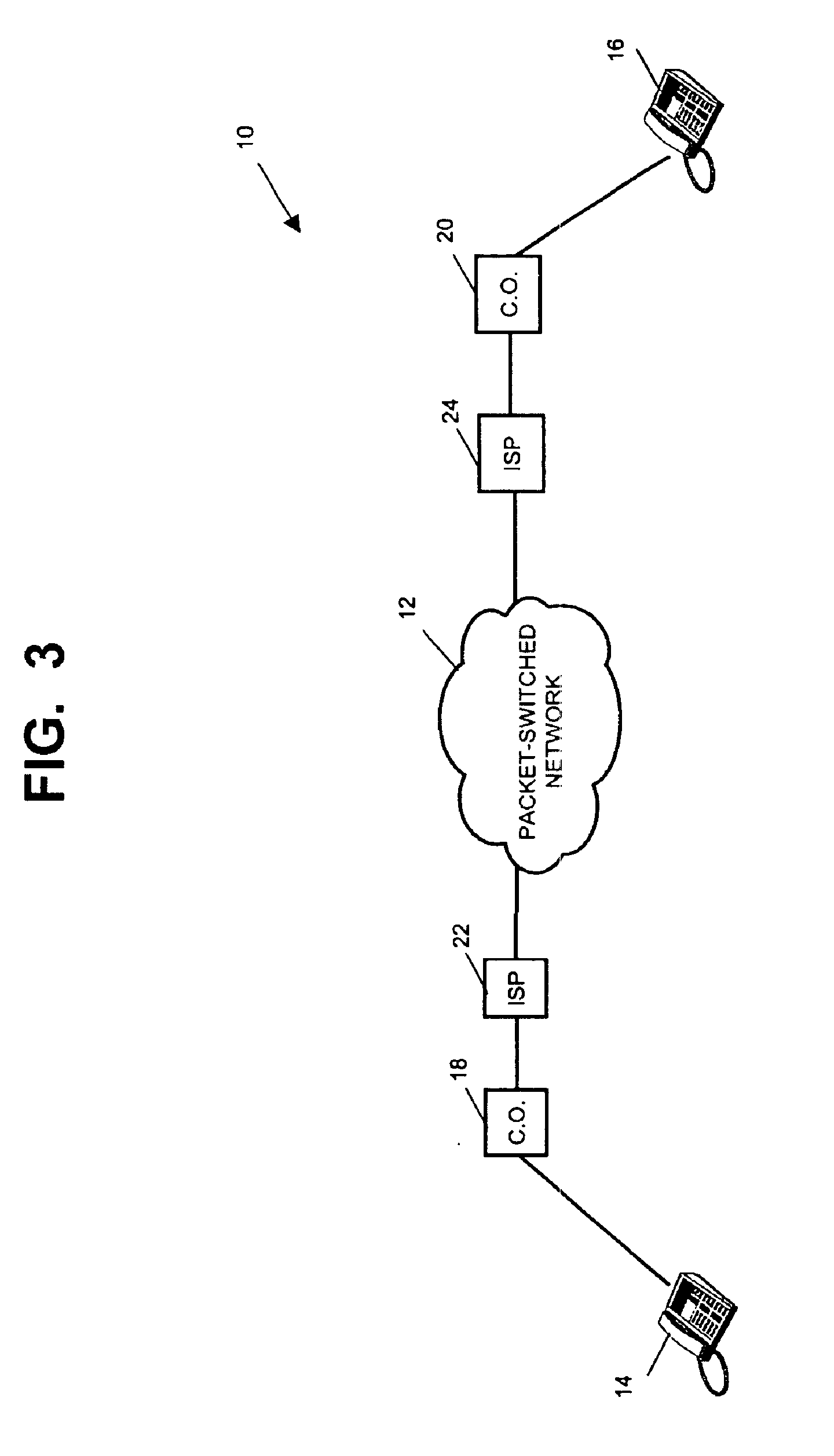
FIG. 3 illustrates one configuration of an Internet telephone call system 10. The Internet telephone call system 10 transports voice over a packet-switched network 12, such as the Internet, using data packets whereby an Internet subscriber (hereinafter “subscriber” and not shown) having the necessary hardware and software may conduct real-time voice conversations over the Internet 12. The Internet devices 14, 16 forming the Internet telephone call system 10 may include a conventional telephone and an adaptor having Internet telephony enabling hardware and software, e.g., the Komodo Fone™ product available from Komodo Technology, Inc. of Los Gatos, Calif. Alternative Internet devices 14, 16, may provide video and other services. Although the Internet telephone call system 10 is illustrated as including telephonic devices, it will be apparent to persons skilled in the art that the present invention can support multimedia audio-visual applications without departing from the scope of th...


PUM


Abstract

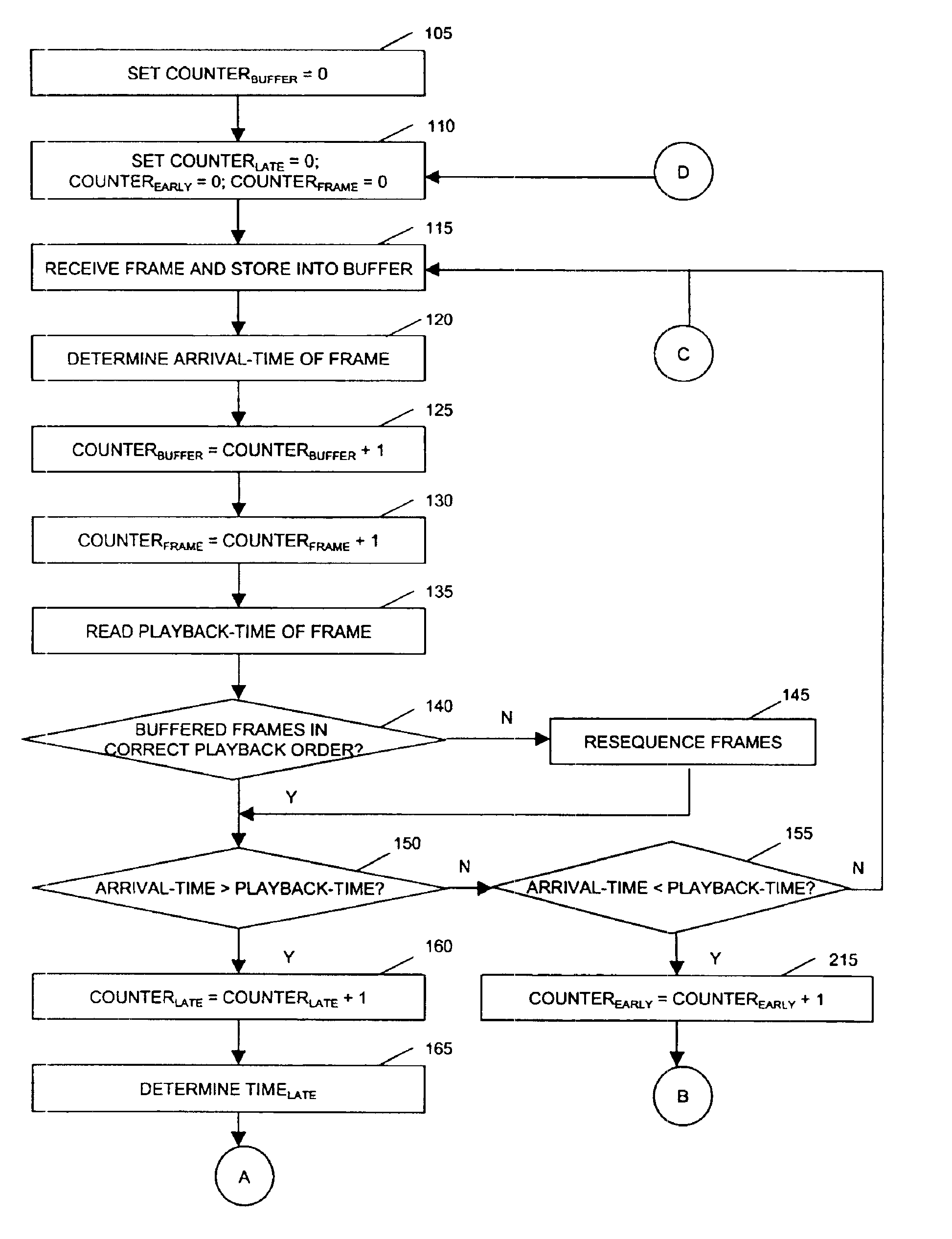
A system and method is disclosed for providing dynamic multimedia jitter buffer adjustment for packet-switched networks. The system temporarily stores an amount of incoming data, which is dynamically adjustable, for an amount of time before sending the data out in a more even stream. The system includes a decoder clock, a jitter buffer, a network jitter statistics collector, and a jitter buffer controller. The decoder clock indicates the arrival-time of the data at the system, while the network jitter statistics collector collects the playback-time of that data. By comparing the arrival-time and the playback-time, the jitter buffer controller determines whether the data arrived on schedule. Accordingly, the depth of the jitter buffer can be adjusted to accommodate the late or early arriving data.

Description

BACKGROUND OF THE INVENTION1. Field of the InventionThe invention relates to a system and method for providing multimedia dynamic jitter buffer adjustment over packet-switched networks.2. Brief Description of the Related ArtNetworks carry three types of information: voice, video, and data. Historically, these different forms of information have been transported over different networks. Specifically, the telephone network delivered voice information; private corporate networks delivered data information; and broadcast networks delivered video information. Each service was provided by a specific form of infrastructure—the telephone network used copper wires to reach subscribers, broadcast television used the airwaves, cable television used coaxial cable, and so forth.With advances in technology, the different forms of information can now be carried by any delivery platform. For example, telephony services (i.e., voice and facsimile) and video services can both be transported over data...

Claims


Application Information

Patent Timeline
IPC IPC(8): H04L12/28H04L29/06
CPCH04L29/06027H04L65/80H04L65/604H04L65/764H04L65/1101
Inventor CHEN, MICHAEL C.
Owner CISCO TECH INC
Learn More