
Microsphere insulation systems

a technology of microspheres and insulation systems, applied in heat-insulating, container discharge methods, other domestic objects, etc., can solve the problems of not preventing the use of materials such as tubes or honeycomb-type cores, and achieve the effect of reducing the effect of moisture and increasing the insulation valu

Inactive Publication Date: 2005-02-22
TECH APPL
View PDF9 Cites 87 Cited by
  • Summary
  • Abstract
  • Description
  • Claims
  • Application Information

AI Technical Summary

Benefits of technology

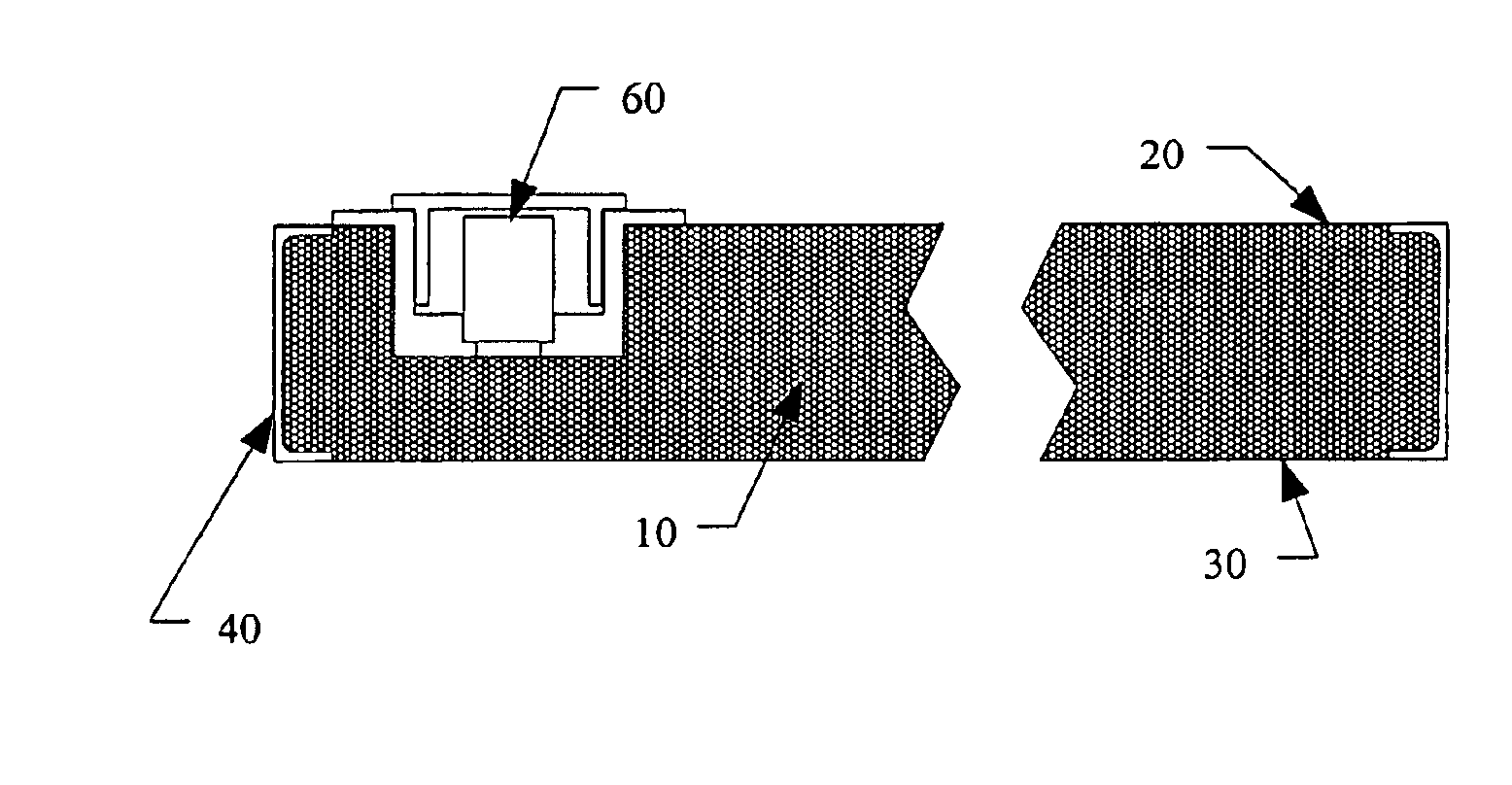
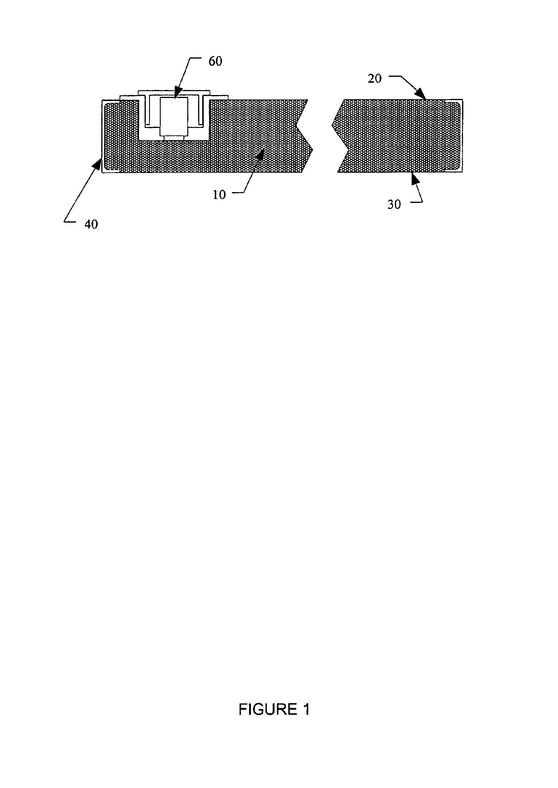
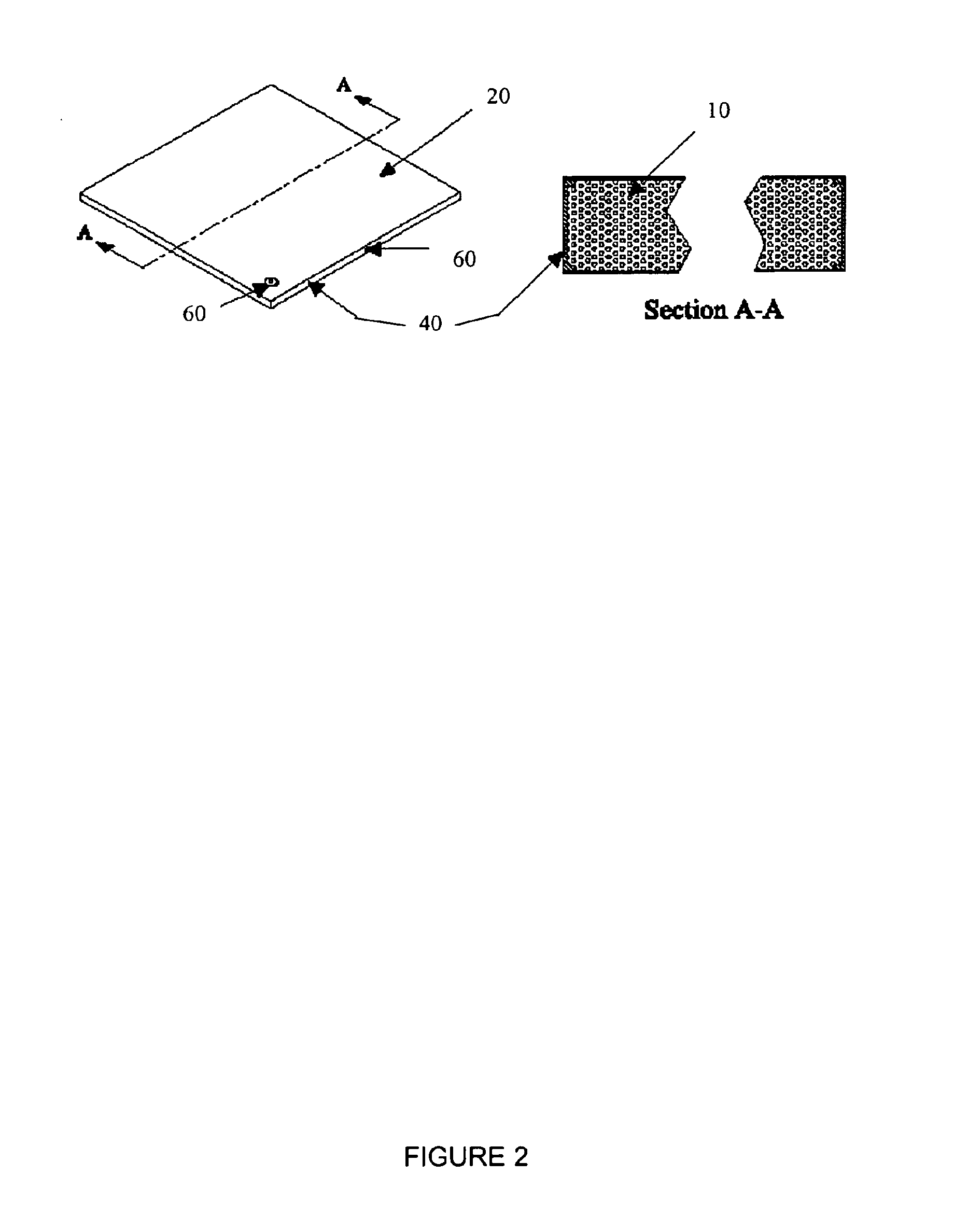
A new insulation system comprising a form filled with microspheres is provided. In separate embodiments, the form may be evacuated or back-filled with a gas. Alternatively, the form may be used after filling with microspheres without evacuation or back-filling. Evacuation of the form increases the insulation value. Back-filling the form with a gas such as argon, nitrogen or carbon dioxide increases the insulation value as compared to ambient. It is preferred that a dry gas be used for back-filling to reduce the effects of moisture on the insulation system.
As used herein, “evacuated” means pressure below ambient. Any pressure below ambient is considered evacuated. By evacuating the form, gaseous conduction is greatly reduced. Any level of evacuation may be used, depending on the preferred insulation level. Some example pressures include less than 760 mm Hg, less than 1 mm Hg, less than 0.1 mm Hg, less than 10−3 mm Hg, less than 10−5 mm Hg and all individual values and ranges therein. The form may be evacuated or back-filled after filling with microspheres to reduce any interference with filling.

Problems solved by technology

As used herein, “filled” means substantially all the open space in the form contains microspheres (there are preferably no channels or other continuous spaces that would prevent the insulation system from fulfilling at least one of the functions outlined herein, for example), but does not prevent the use of materials such as tubes or a honeycomb-type core to obtain or maintain the desired pressure inside the form or provide structural support.

Method used


Image

  • Microsphere insulation systems
  • Microsphere insulation systems
  • Microsphere insulation systems

Examples


Embodiment Construction

The invention may be further understood by reference to the following non-limiting examples, description and figures, where like numbers indicate like features.

The microsphere insulation system offers the ability to fabricate lightweight insulation systems that can be produced in complex shapes for aerospace and other applications including high efficiency storage vessels and transfer lines, along with flat or curved panels for operation at a wide variety of temperatures. The load bearing capability allows the performance of vacuum insulation without heavy self-supporting vacuum jacketing.

The insulation system may be used in a variety of operating pressure and temperature conditions, including ambient and reduced pressure. The selection of pressure required is determined by the level of insulation desired in a given application, and is easily determined without undue experimentation by one of ordinary skill in the art. Some applications for this invention include insulation of cryog...


PUM

PropertyMeasurementUnit
Percent by volumeaaaaaaaaaa
Densityaaaaaaaaaa
Volumeaaaaaaaaaa

Abstract

A new insulation system is provided that contains microspheres. This insulation system can be used to provide insulated panels and clamshells, and to insulate annular spaces around objects used to transfer, store, or transport cryogens and other temperature-sensitive materials. This insulation system provides better performance with reduced maintenance than current insulation systems.

Description

BACKGROUND OF THE INVENTIONInsulation of transfer lines and storage vessels for cryogens and other temperature-sensitive materials is required to prevent transfer and storage losses, and to reduce other economic losses such as maintenance and replacement costs.Currently transfer line insulation can be grouped into three general categories: vacuum-jacketed multilayer insulation (MLI), powders (e.g., perlite), and solid foams, (e.g., polyurethane). Vacuum-jacketed lines with MLI have the lowest heat leak; however, they have high initial cost and require periodic vacuum maintenance. Evacuated powder insulation is less expensive, but has lower thermal performance, and therefore is not generally used for transfer line insulation. Polyurethane foam insulation is used on many large cryogenic transfer lines because of its low initial cost and relative ease of installation. However, it has a much higher heat leak than evacuated MLI and is subject to severe degradation from repeated thermal c...

Claims


Application Information

Patent Timeline
IPC IPC(8): E04B1/80F16L59/06F16L59/065F17C13/00E04B1/74
CPCE04B1/803F16L59/065F17C13/001Y10T428/231Y02B80/12F17C2203/0329F17C2203/0341F17C2203/0345F17C2203/0358F17C2203/0391F17C2221/011F17C2221/012F17C2221/014F17C2221/016F17C2221/017F17C2221/033F17C2223/0161F17C2223/033F17C2270/0186Y02E60/321Y10T428/1393E04B2001/748Y02A30/242Y02B80/10Y02E60/32
Inventor ALLEN, MARK S.WILLEN, GARY S.MOHLING, ROBERT A.
Owner TECH APPL
Learn More