
Process and equipment for manufacturing clear, solid ice of spherical and other shapes

a technology of solid ice and clear ice, which is applied in the direction of ice production, lighting and heating apparatus, food processing, etc., can solve the problems of large energy consumption, large energy consumption, and typical unclear ice clouded core, and achieves less tight contact, precise ice production, and good molding precision

Inactive Publication Date: 2005-02-22
SOMURA KATSUZO
View PDF11 Cites 82 Cited by
  • Summary
  • Abstract
  • Description
  • Claims
  • Application Information

AI Technical Summary

Benefits of technology

This fast freezing ability is convenient when juice and other solutions are to be frozen, because juice is frozen before separation will take place.
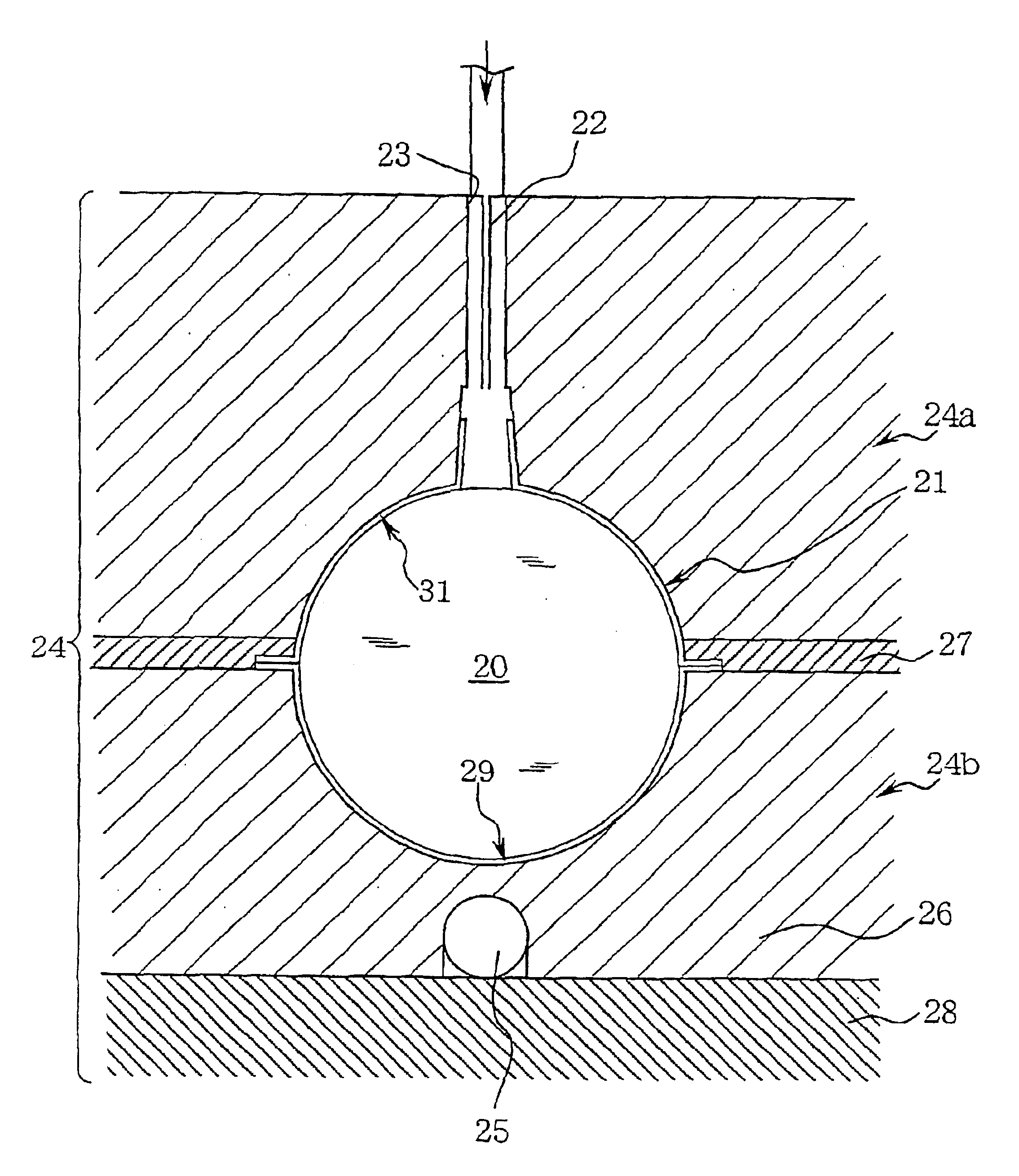
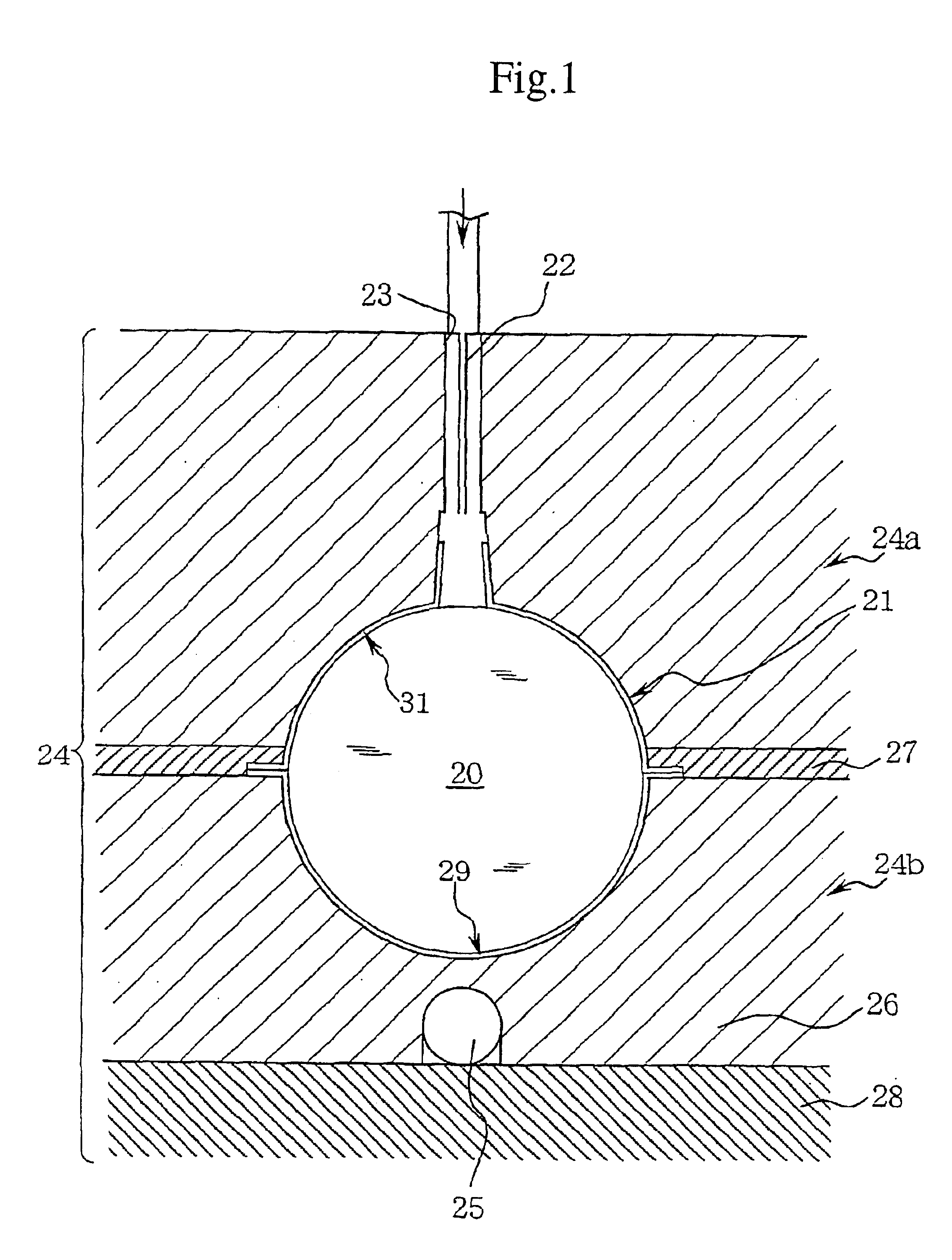
Ice on the bottom of the spherical container receives coldness from the water-freezing block, and ice itself becomes an ice-cold source, which freezes up at once the intermittently injected water sprayed on the frozen water. Like icicle formation, thin clear laminated ice is obtained by this most reliable, most efficient ice-making method. The upper mold is a heat-insulating material that confines coldness of the lower part. This mechanism is energy saving and economic because the entire space in the spherical container to be filled with ice can be cooled by means of only the water-freezing block.
The water-freezing block can be a big one if the block is designed to give a thick configuration. When another round of freezing operation starts, a thick freezing block is advantageous because the previously produced ice does not affect the thick block even if coldness is drawn therefrom, and so the subsequent ice can be made quickly. (Ice cold source need not be operated more powerfully than usual.)
An insulating sheet (a container) stands between the inner surface of the mold and ice to prevent ice from coming in contact with the water-freezing block. Because this insulating sheet serves as a mold-release agent, it is easy to release ice from the mold and to take ice out of the mold (with no requirement for heating).
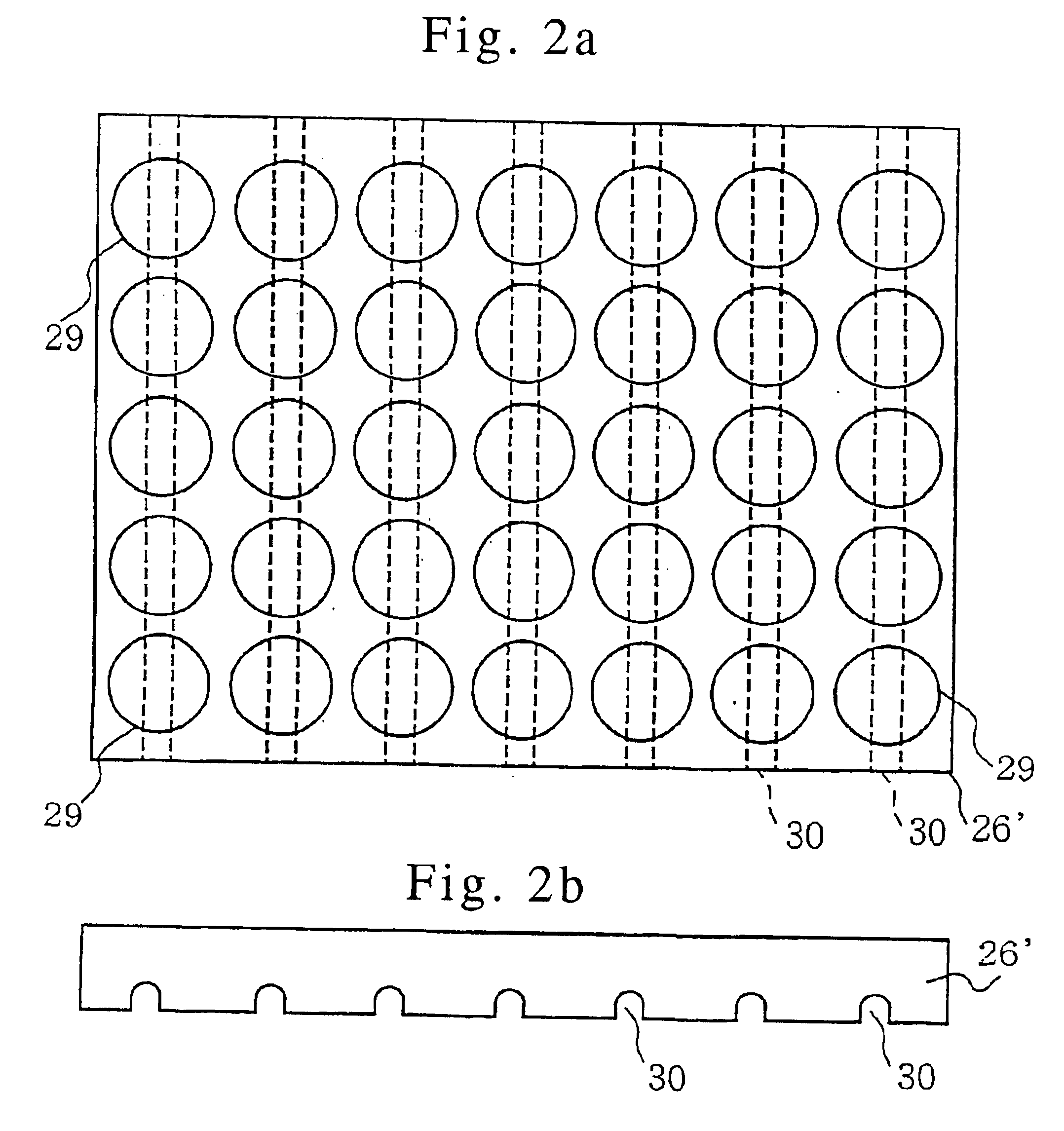
It is contemplated that a resinous sheet material such as styrol, may have less tight contact with the mold because of its flexibility even if the resinous sheet has good molding precision. Because of a heat-insulating air layer existing inside the container as an intervention and the resistance of the resin itself to thermal conductivity, it is possible to think of a fear that the surface of sprayed water may not have a predetermined freezing temperature and therefore that precise ice production cannot be expected. There is no such concern in the case of a metal plate material, such as aluminum, which is a hard and good thermal conductor. This is because metal plates secure thermal conductivity by way of the unavoidable contact with the water-freezing block, ie., the cold source, even if the container has less molding precision and incomplete contact with the mold. And there may happen non-uniform temperature distribution among separately configured freezing blocks, and it may become impossible to make uniform ice. Even if such a problem occurs, non-uniform temperature distribution among blocks can be solved conveniently by inserting a thermally conductive plate, such as an aluminum plate, between two adjacent freezing blocks in a manner that the plate can be contacted with each spherical container.

Problems solved by technology

In that case, the upper and lower portions freeze first, and the middle portion, especially the core portion, is the last to be frozen, thus resulting in typical unclear ice having clouded core.
(1) After raw water is ejected, water is collected except for the iced portion, and is re-jected. In other words, water is recycled and reused. Because of this recycling, the opening 18 is clogged up with ice before round ice is completed. (Since recycled water tends to have a temperature at which water is frozen easily, the opening 18 begins freezing and clogging.) Eventually, it seems that solid block of ice fails to complete.
(2) It is reported that freezing takes place not only in the ice-making cup 11 equipped with the coolant pipe 15, bat also on the covers 12, 12. It means that cooling is necessary for the space under substrates 13 where there are the covers 12, 12 and therefore that strong freezing equipment is required for this purpose. As regards the ice-making cups 11, the coolant pipe 15 is inefficient because it is tied around the head portion of the cup 11, and a major part of the pipe 15 is exposed to air. Enormous energy is thus required to cool both of the ice-making cup 11 and ambient air surrounding the covers 12, 12.
(3) This enormous energy is not utilized efficiently. It is rather wasted because the ice-making process requires discontinued operation, energy loss, and repeated release of energy. For example, after ice balls are formed within the cup 11 and the covers 12, 12, hot gas is passed through the coolant pipe 15. In addition, water of normal temperature is ejected onto the covers 12, 12 from the nozzles 16. Then, when ice-making process resumes, the coolant pipe 15 and the covers 12, 12 have to be cooled again. This is inefficient utilization of heat.

Method used


Image

  • Process and equipment for manufacturing clear, solid ice of spherical and other shapes
  • Process and equipment for manufacturing clear, solid ice of spherical and other shapes
  • Process and equipment for manufacturing clear, solid ice of spherical and other shapes

Examples


Embodiment Construction

This invention is further described in the case of ice balls, now referring to FIGS. 1-17.

FIG. 1 shows an overall configuration of the equipment for making a clear ice ball in the preferred embodiment of this invention (the mold and the spherical container of the type divided into upper and lower halves), in the state in which ice has been completed. The ice ball 20 is packed in the container 21, which in turn is abut in the mold 24 for making ice balls. This mold 24 comprises an upper mold 24a and a lower mold 24b. The former is made of a heat-insulating material and is provided with an injection nozzle 22 that is connected to an intermittent injection mechanism; the latter is the water-freezing block 26, in which the coolant pipe 25 is embedded (In FIG. 1, the pipe is located right under the mold).

In FIG. 1, a rubber gasket layer 27 is disposed preferably on the underside of the upper mold 24a, and is used for the sake of completeness to put the container exactly between both halv...


PUM


Abstract

The process and equipment, according to this invention, for manufacturing clear, solid ice of spherical and other shapes are capable of making clear ice balls and block ice of other shapes in the mold quickly, efficiently, and with effective energy utilization. This process is characterized in the steps of:a) preparing a mold for making ice balls and block ice of other shapes, which comprises an upper mold (24a) made of an insulating material and provided with a vertical injection hole (23) drilled therein and a water-injection nozzle (22) fitted in the hole; and a lower mold (24b) made of a water-freezing block (26) having coolant pipe (25) embedded therein;b) preparing for a domed lid (21a) or the lid of a different shape made of an insulating sheet, said lid (21a) having a shape that fits in with the surface shaped for the upper mold (24a) and being provided with a cylinder for being fitted into the vertical injection hole (23); and a shaped hemispherical cup (21b) of the same insulating sheet, which similarly fits in with the shaped surface of the lower mold (24b);c) assembling both halves of the mold (24) after the lid (21a) and the cup (21b) have been attached tightly to each other and placed in the mold;d) then, keeping the liquid to be frozen cooled at a predetermined temperature and spraying the liquid intermittently in the direction of the water-freezing block (26) that has been cooled to a predetermined freezing temperature;e) repeating the spraying operation to freeze the sprayed liquid in the container (21), layer by layer, until clear ice balls (20) or block ice of other shapes are formed; andf) disassembling the halves of the mold under the ice-releasing effect, which the ice container (21) has on the ice-making mold (24), and immediately taking out We shaped ice balls (20) or the block ice of a different shape.

Description

TECHNICAL FIELDThis invention relates to the process and equipment for manufacturing clear ice balls of the type frozen in the mold. These ice balls according to this invention are used for drinks to cool spirits and alcoholic beverages and are equivalent to those ice balls that are shaped by the bartender from clear ice by cutting it with artisan skill, or are shaped into balls with the grinder from block ice, put in a glass and served to the customer who has ordered a glass of alcoholic beverage. The size of ice balls ranges from too big one to put in the mouth to the balls as small as a piece of candy. These ice balls belong to a different field in use and size from the ice for shot blast or from small ice for instant cooling use, but are manufactured in the form. And as such, the process and equipment of this invention should also be applied to other types of shaped ice capable of being released from the mold.There have been various proposals on the manufacture of ice balls of t...

Claims


Application Information

Patent Timeline
IPC IPC(8): F25C1/22F25C1/18
CPCF25C1/22F25C1/18Y02P60/85F25C1/25
Inventor SOMURA, KATSUZO
Owner SOMURA KATSUZO
Learn More