Eureka AIR delivers breakthrough ideas for toughest innovation challenges, trusted by R&D personnel around the world.

Method and system for designing a network

a network and network technology, applied in the field of networks, can solve the problems of ineffective call-attempt requirements, inability to meet drop-call requirements, and inability to meet availability measurement,

Inactive Publication Date: 2005-02-15
RPX CLEARINGHOUSE
View PDF18 Cites 32 Cited by
  • Summary
  • Abstract
  • Description
  • Claims
  • Application Information

AI Technical Summary

Benefits of technology

It is therefore an object of the present invention to provide a novel method and system for de

Problems solved by technology

However, an availability measurement may not be useful in designing or measuring networks transporting critical applications.
For example, a “Five-Nines Availability” may not be acceptable for voice access, because the availability measurement does not reflect other measurements such as failure frequency, failure duration and failure impact:—all critical attributes to users of networks.
If, however, the “Five-Nines” is one-hundred-and-fifty, two-second outages, then the subscriber outage requirements are met but ineffective call-attempt requirements and dropped-call requirements are generally not met.
The foregoing example shows how an availability measurement can be unhelpful in designing PSTNs, but it will now be apparent to those of skill in the art that such availability measurements are even further ineffectual in the design, monitoring and optimization of more modem, multi-service networks that carry fax, data, voice, video, audio and other forms of electronic communications.
It will be further apparent that the foregoing problems are exacerbated where services are delivered to the user across multiple networks controlled by various different network providers.

Method used


Image

  • Method and system for designing a network
  • Method and system for designing a network
  • Method and system for designing a network

Examples


Embodiment Construction

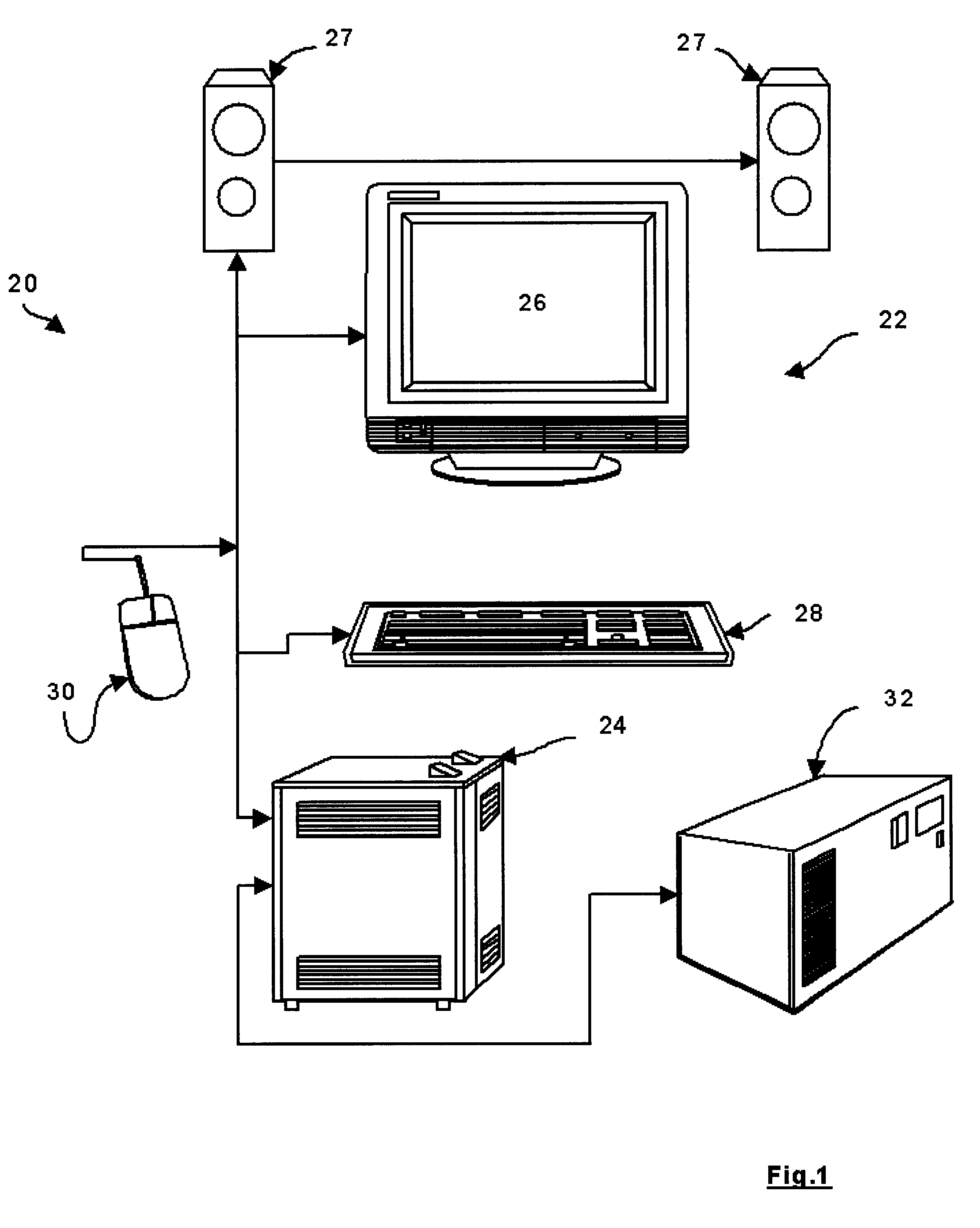
Referring now to FIG. 1, a system for designing a network is indicated generally at 20. In a present embodiment, system 20 is a computer 22 having a processing unit 24 that generates user-output to one or more user-output devices, which in a present embodiment includes a monitor 26 and speakers 27. Monitor 26 can be a cathode-ray tube, an electroluminescent display, an active matrix display and / or any other user-output display device, as will occur to those of skill in the art. Processing unit 24 receives user-input from user-input devices which in a present embodiment include a keyboard 28 and a pointing-device or mouse 30. Processing unit 24 is connected to a persistent storage device which in a present embodiment is a hard-disc drive 32.

One suitable configuration of processing unit 24 includes a mother-board bearing a Pentium III microprocessor, one-hundred-and-twenty-eight megabytes of random access memory, and a video-output card that generates signals for presentation as an im...


PUM


Abstract

The present invention provides a novel system and method for designing a network. The system is preferably a computer operable to allow a user to input the nodes and links of a network, and to input product information associated with the nodes and links. The computer also stores product-reliability models corresponding to the hardware information. The computer is operable to perform operations that consider the nodes, links, product models to determine a set of reliability performance parameters. The computer can be further operable to vary certain reliability parameters to determine the impact from the perspective of an end-user or other type of network client. One method can include the collection of desired client requirements from the end-user and designing various network configurations to conform with the desired client requirements. Thus, the present invention can be used, and to optimize network designs. Another application is to incorporate the tool in network management product to be used to build or enhance existing networks. This function could be both static as well as dynamic. Thus, the present invention can also be used for other purposes such as modifying, monitoring or optimising existing networks.

Description

FIELD OF THE INVENTIONThe present invention relates generally to networks and more particularly relates to a system and method for designing a networks.BACKGROUND OF THE INVENTIONA well-known type of network is the Public Switched Telephone Network (“PSTN”). The PSTN was originally intended to carry voice communications over telephone lines, however, they are increasingly used to carry electronic data, such as facsimile transmissions and / or modem communications. The internet is another network that is gaining enormous popularity. The internet has typically been used to carry electronic data. However, as bandwidths increase and digitization (such as MPEG) improves, the Internet will increasingly be used to carry voice and video communications. In general, it can be seen that known networks are converging. For example, the distinction between PSTN and Internet will become less meaningful as a single type of network becomes capable of carrying voice, fax, video, data and other forms of...

Claims


Application Information

Patent Timeline
IPC IPC(8): G06F15/16G06F15/173H04L12/24
CPCH04L41/0659H04L41/5009H04L41/5006H04L41/5003
Inventor PATERSON, ROBERT K.SAND, ALLAN I.MAR, ANTHONY L.
Owner RPX CLEARINGHOUSE
Why Eureka
Eureka Blog
Learn More