
Method of operating a hybrid electric vehicle to reduce emissions

a hybrid electric vehicle and electric vehicle technology, applied in hybrid vehicles, electrical control, exhaust treatment, etc., can solve the problems of reducing the time during which the catalytic converter is least efficient, poor efficiency of the catalytic converter, and prior efforts have suffered from some drawbacks, so as to reduce the power output of the internal combustion engine, reduce emissions, and reduce emissions.

Inactive Publication Date: 2005-02-15
FORD GLOBAL TECH LLC
View PDF18 Cites 29 Cited by
  • Summary
  • Abstract
  • Description
  • Claims
  • Application Information

AI Technical Summary

Benefits of technology

The invention provides a method for reducing emissions in a hybrid electric vehicle by selectively increasing or decreasing the power output of the engine using the vehicle's motor / generator. This can be done during cold-start conditions or when the vehicle is undergoing a transient event. The method can also involve reducing the load changes experienced by the engine during these events, which can lead to increased efficiency of the catalytic converter and further reduction of emissions. Overall, the method improves the vehicle's performance and reduces harmful emissions.

Problems solved by technology

Due to the relatively poor efficiency of the catalytic converter prior to “light-off”, recent efforts to reduce tailpipe emissions have concentrated on reducing the “light-off” time, thereby reducing the time during which the catalytic converter is least efficient.
These prior efforts have also included concomitantly altering the air-fuel ratio and / or retarding the spark calibration of the engine.
These prior efforts have suffered from some drawbacks.
Particularly, the difficulty in controlling the combustion stability of the engine and the operating load of the engine as it warms up severely limits these prior strategies.
Hence, these methods which concentrate on cold-start type operating conditions do not adequately address or improve emissions during transient events once the vehicle has warmed up.
While hybrid electric vehicles significantly reduce emissions, the foregoing emissions reducing strategies are not well-suited for use with hybrid electric vehicles.
Particularly, the foregoing emissions reducing strategies do not maximize and / or utilize the flexibility of hybrid electric vehicles to utilize both an electric motor and an internal combustion engine to provide power and torque.

Method used


Image

  • Method of operating a hybrid electric vehicle to reduce emissions
  • Method of operating a hybrid electric vehicle to reduce emissions
  • Method of operating a hybrid electric vehicle to reduce emissions

Examples


Embodiment Construction

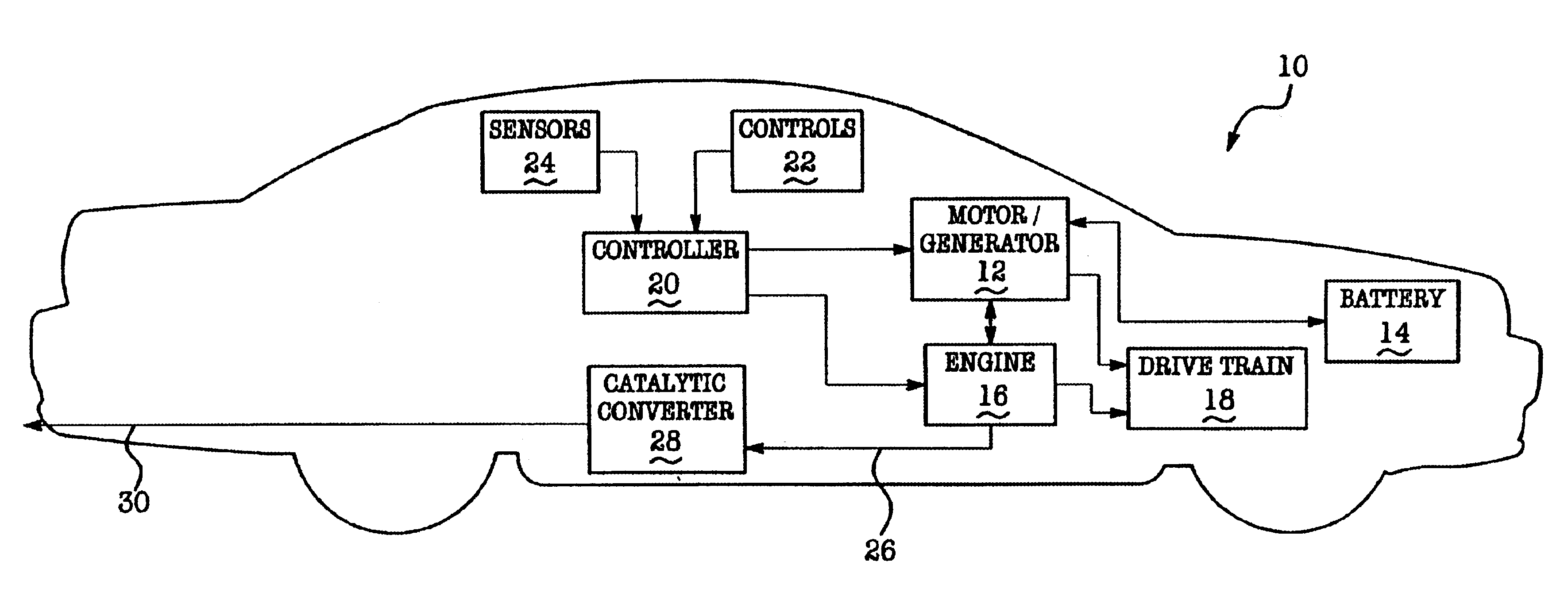
Referring now to FIG. 1, there is shown an automotive hybrid electric vehicle (“HEV”) 10 which utilizes a method or strategy for reducing emissions which is performed in accordance with the teachings of the preferred embodiment of the present invention. Vehicle 10 includes an electric machine or motor / generator 12, which is operatively coupled to a conventional electrical energy storage device 14 (e.g., a battery, fuel cell or other electrical energy storage device), and an internal combustion engine 16. Motor / generator 12 and engine 16 are each selectively and operatively coupled to the vehicle's driveline or drive train 18 (e.g., to the drive shaft(s) of the vehicle) and cooperatively deliver power and torque to the drive train 18, thereby powering the vehicle 10. A control system or controller 20 is electrically and communicatively coupled to motor 12, engine 16, conventional user or driver operated controls or components 22, and conventional vehicle operating condition sensors 2...


PUM


Abstract

A method of operating a hybrid electric vehicle 10 to reduce emissions. The method utilizes the vehicle's electric motor / generator 12 to generate a negative torque during cold-start conditions, effective to increase the load on the internal combustion engine 16, thereby reducing the light-off time of the catalytic converter 28. The method also reduces emissions by utilizing the vehicle's motor / generator 12 to provide a supplemental torque to engine 16 during transient events, thereby reducing the generated mass flow and amount of untreated emissions.

Description

BACKGROUND OF INVENTION1. Field of the InventionThis invention relates to a method of operating a hybrid electric vehicle to reduce tailpipe emissions and more particularly, to a method of operating a hybrid electric vehicle which utilizes the vehicle's electric motor / generator to reduce emissions during cold-start and transient conditions.2. Background ArtConventional vehicles having internal combustion engines utilize a three-way-catalyst (“TWC”) to reduce tailpipe emissions. Particularly, the TWC catalytically reduces nitrogen oxides (NOx) and oxidizes carbon monoxide (“CO”) and unburned hydrocarbons (“HC”) which are produced during the combustion process. The TWC has a very high conversion efficiency once the catalyst has “warmed up” and the air-fuel ratio of the mixture is near its stoichiometric point. An example of the conversion efficiency of a typical catalytic converter over time is shown in graph 100 of FIG. 5.In conventional vehicles, more than fifty percent (50%) of the...

Claims


Application Information

Patent Timeline
Patent Type & Authority Patents(United States)
IPC IPC(8): B60K6/04B60K6/00F02D41/02B60K6/485B60L50/16B60W10/06B60W10/08B60W20/00B60W30/192F01N9/00
CPCB60K6/485B60W10/06B60W10/08B60W20/00F02D41/0255B60W20/1082Y02T10/6226Y02T10/54Y02T10/6286Y02T10/26B60W30/192F02D2041/026B60W20/16Y02T10/12Y02T10/40Y02T10/62B60W20/15
Inventor PETERS, MARK WILLIAMBOGGS, DAVID LEE
Owner FORD GLOBAL TECH LLC
Learn More