
High-frequency current generating circuit and control device for controlling light intensity of laser diode

Inactive Publication Date: 2005-02-15
KK TOSHIBA
View PDF15 Cites 7 Cited by
  • Summary
  • Abstract
  • Description
  • Claims
  • Application Information

AI Technical Summary

Benefits of technology

The main object of the present invention is to provide a high-frequency current generating circuit included in a semiconductor integrated circuit, this current generating circuit being able to increase the amplitude of a high-frequency current superimposed on the control current of a laser diode and generate less heat while suppressing power consumption, and control device for controlling light intensity of laser diode.

Problems solved by technology

When a laser diode is employed in an optical pickup device, a problem of occurrence of so-called return-light noise arises.
The occurrence of the return-light noise is a phenomenon that when a light beam emitted from the laser diode is applied onto an optical disk, a part of the reflected light returns from a optical disk surface to the laser diode to thereby generate noise.
Then, the intensity of output light varies greatly, and return-light noise occurs as stated above.
This circuit, however, generates considerable heat.
It is, therefore, difficult to arrange the high-frequency current generating circuit in the vicinity of the laser diode.
When the frequency of such a superimposed high-frequency current increases and so does the junction capacitance of the laser diode increase, driving loss rises.
As a result, the power consumption of the high-frequency current generating circuit increases, thereby making it quite difficult to arrange a high-frequency current generating circuit in the vicinity of the laser diode.
Even so, the same disadvantages occur if two independent high-frequency current generating circuits corresponding to the respective wavelength are provided.
The first disadvantage is caused by providing light detectors for monitoring the intensity of light, these detectors being individually provided to correspond to the respective laser diodes.
If so, the number of pins of the package for packaging the laser diode and the light detector of monitoring light intensity, disadvantageously increases.
Another disadvantage is that if a monolithic structure in which two laser diodes are formed in one chip is employed, this structure requires an optical device, such as a dichroic prism, having wavelength selectiveness and separating an optical path so as to separate light of the respective wavelength from each other and to allow the separated light to be incident on the respective light-monitoring detectors.
As a result, the size of the package becomes large.
These disadvantages are serious obstructions to realizing a smaller, thinner and lighter optical pickup device.
Accordingly, in one light-monitoring detector, it is difficult to accurately control the intensity of light of each laser diode.
As described above, according to the conventional high-frequency current superposition technique, if the frequency of the high-frequency current superimposed on the control current of the laser diode increases due to high rate of transmitting data, the junction capacitance of the laser diode increases and thereby driving loss increases, then it is required to increase the amplitude of the superimposed high-frequency current.
Consequently, the power consumption of the high-frequency current generating circuit increases to thereby generate more heat.
It is, therefore, difficult to provide a smaller, thinner optical pickup device by providing a high-frequency current generating circuit in the vicinity of a laser diode.

Method used


Image

  • High-frequency current generating circuit and control device for controlling light intensity of laser diode
  • High-frequency current generating circuit and control device for controlling light intensity of laser diode
  • High-frequency current generating circuit and control device for controlling light intensity of laser diode

Examples


first embodiment

(First Embodiment)

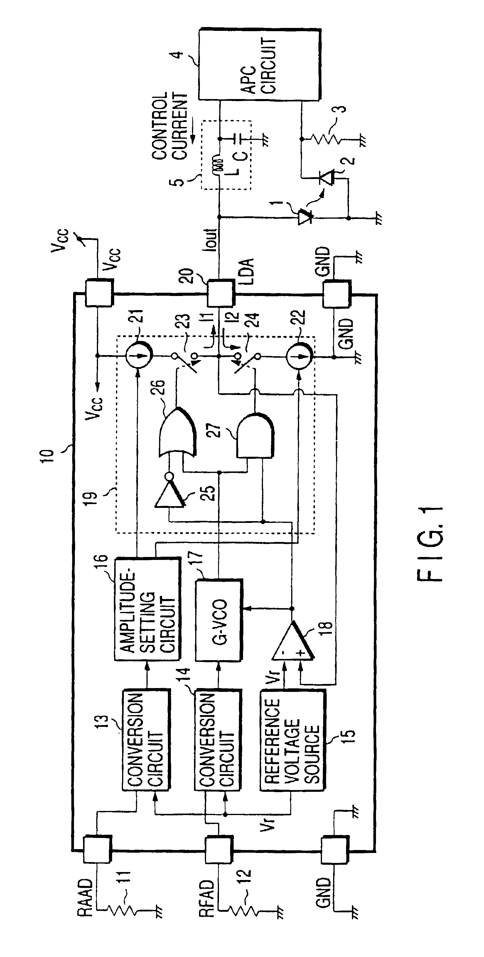
FIG. 1 is a circuit diagram showing the overall arrangement of a semiconductor device including a high-frequency current generating circuit according to the present invention. This semiconductor device consists of a laser diode 1, a light-monitoring detector 2 for monitoring light intensity, a current-to-voltage conversion resistor 3, an APC (auto-power control) circuit 4, a high-frequency blocking filter 5 and a high-frequency current generating circuit 10.

The laser diode 1 constitutes, for example, the light source of an optical system unit to be described later and generates a laser beam to be applied onto an optical disk such as a DVD. Part of the light emitted from the laser diode 1 is received by the light-monitoring detector 2. The light-monitoring detector 2 is, for example, a photo-diode. The detector 2 detects the intensity of light emitted from the laser diode and generates a corresponding output current. The output current of the light-monitoring detect...

second embodiment

(Second Embodiment)

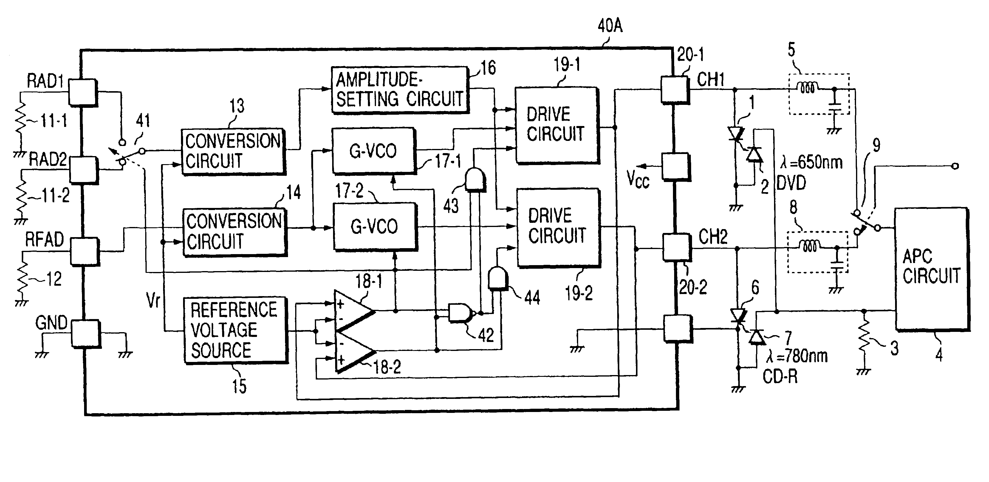
Now, the second embodiment of the present invention will be described with reference to FIG. 9. FIG. 9 shows an example of applying the present invention to a semiconductor device for selectively driving two laser diodes emitting light having a different wavelength.

Description will be given while the same constituent elements shown in FIG. 9 as those in FIG. 1 are denoted by the same reference symbols. In this embodiment, a laser diode 6 is provided in addition to the laser diode 1. It is assumed that the first laser diode 1 emits light at a light emission wavelength of, for example, λ=650 nm corresponding to a DVD and the second laser diode 6 emits light at a light emission wavelength of, for example, λ=780 nm corresponding to a CD-ROM.

In addition, a light-monitoring detector 7 of detecting light intensity and a high-frequency blocking filter 8 are newly provided, corresponding to the addition of the second laser diode 6. The cathode terminals of the two light-mo...

third embodiment

(Third Embodiment)

Now, the third embodiment of the present invention will be described with reference to FIG. 10. This embodiment concerns, as in the case of the second embodiment, a case where the present invention is applied to a semiconductor device for selectively driving two laser diodes having a different light emission wavelength, respectively.

Description will be given hereinafter, while the same constituent elements in FIG. 10 as those shown in FIG. 9 are denoted by the same reference symbols. In the embodiment shown in FIG. 9, light-monitoring detectors 2 and 7 for detecting light intensity corresponding to the two laser diodes 1 and 6 are provided, respectively. In this embodiment, by contrast, one common light-monitoring detector 2 receives light beams emitted from laser diodes 1 and 6.

As shown in FIGS. 11A and 11B, the laser diodes 1 and 6 are so-called monolithic two wavelength integrated laser diodes (TWIN-LD). A light-monitoring detector 2 is so arranged as to detect ...


PUM


Abstract

In a laser-driving device including a high-frequency current generating circuit generating a high-frequency current superimposed on a control current output from a light intensity control circuit for light intensity control, and supplied to a laser diode as a drive current, the high-frequency current generating circuit has a sourcing current source, a sinking current source, current switches connected between the current sources and a drive output terminal respectively, a gated oscillation circuit oscillating with a desired frequency, and switch drive circuits complementarily on / off controlling the current switches by using a drive switching signal obtained by removing a high-frequency component from an output signal of the oscillation circuit. The present invention, therefore, provides a high-frequency current generating circuit which can increase the amplitude of the high-frequency current superimposed on the control current of the laser diode and which generates less heat while suppressing power consumption.

Description

BACKGROUND OF THE INVENTIONThe present invention relates to a high-frequency current generating circuit for reading a signal recorded on an optical-recording medium which is a disk-type data storage medium (to be referred to as “optical disk” hereinafter) from / to which information is read and / or written by a laser beam, and relates to a controller for controlling the light intensity of a laser diode.Recently, optical disk devices such as a CD-ROM (Compact Disk Read-Only Memory) device, a CD-R (Compact Disk Recordable) device, a CD-RW (Compact Disk Rewritable) device and DVD (Digital Versatile Disk) device, are widely used as storage devices provided externally of, for example, a personal computer which is an information processor for processing information. In addition, portable equipment such as a notebook computer handy to carry and mobile equipment which is easily movable, are popular. As a consequence, demand for increasing the storage capacitance of an optical disk device insta...

Claims


Application Information

Patent Timeline
IPC IPC(8): H01S5/0683H01S5/042H01S5/00G11B7/125
CPCH01S5/0683H01S5/042
Inventor TAGUCHI, TOYOKI
Owner KK TOSHIBA
Learn More