
Digital voltage regulator using current control

a voltage regulator and digital technology, applied in the field of voltage regulators, can solve the problems of loss of information, degraded analog signals, and expensive analog circuits, and achieve the effects of reducing current ripple, convenient form factor, and reducing the use of analog circuits

Inactive Publication Date: 2005-02-08
VOLTERRA SEMICONDUCTOR
View PDF34 Cites 103 Cited by
  • Summary
  • Abstract
  • Description
  • Claims
  • Application Information

AI Technical Summary

Benefits of technology

Advantages of the invention may include the following. The voltage regulator handles relatively large currents reacts quickly to changes in the load. The voltage regulator may use small capacitors with a convenient form factor. The voltage regulator can include multiple slaves which are operated out of phase in order to reduce current ripple. The use of analog circuits is minimized by converting analog measurements in the controller into digital signals. The controller may be implemented using mostly digital circuitry, and may be fabricated using known processes through conventional complementary metal oxide semiconductor (CMOS) fabrication techniques. This reduces the number of off-chip components in the controller. The controller operates with a digital control algorithm in which the operating parameters may be modified to adapt the voltage regulator for different applications. The digital control algorithm can operate at clock frequency significantly higher than the switching frequency, allowing quick response to changes in the load. The master and slaves can communicate with digital signals, thereby providing improved communication reliability.

Problems solved by technology

Unfortunately, analog circuits are expensive and / or difficult to fabricate as integrated circuits.
In addition, analog signals can be degraded by noise, resulting in a loss of information.

Method used


Image

  • Digital voltage regulator using current control
  • Digital voltage regulator using current control
  • Digital voltage regulator using current control

Examples


Embodiment Construction

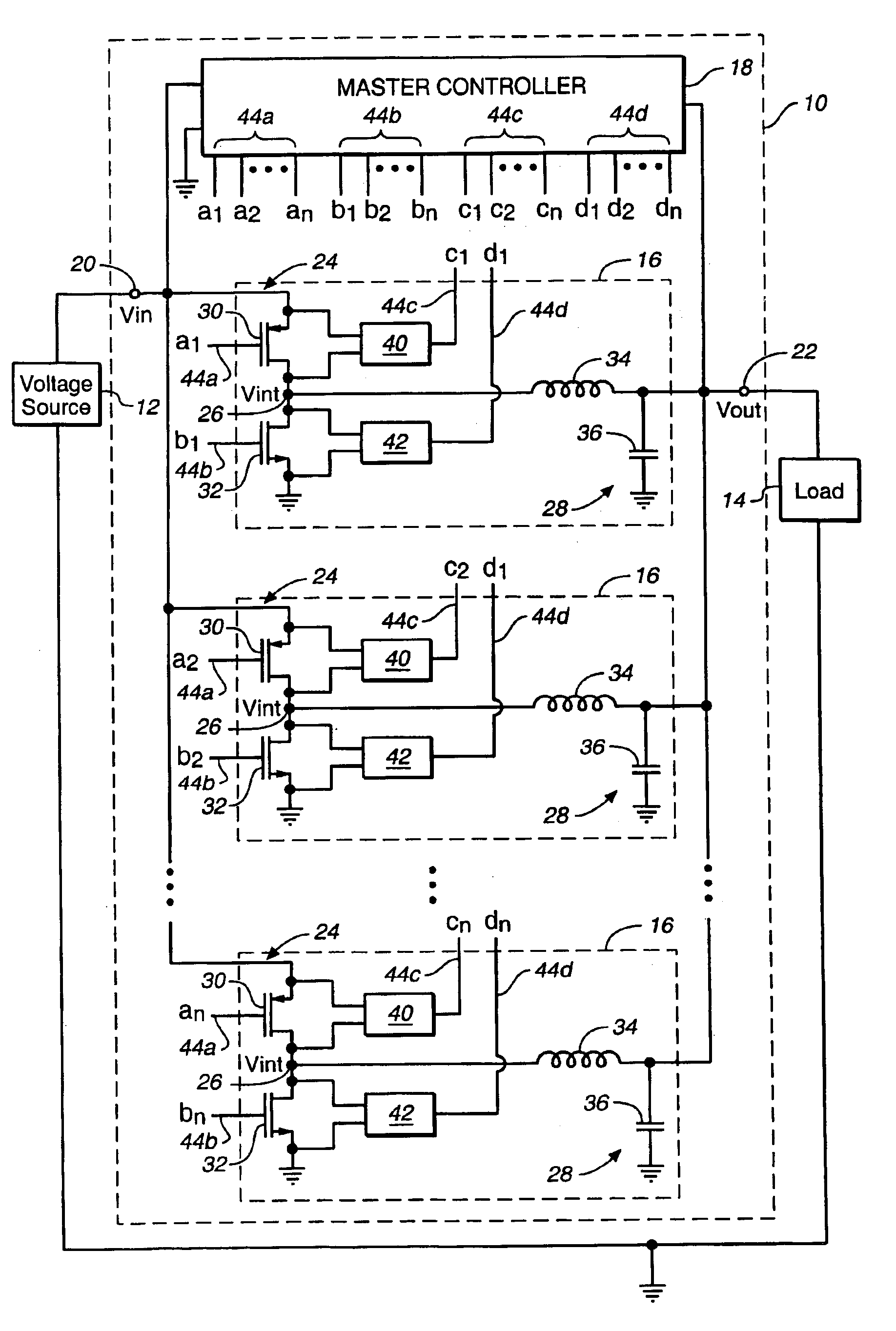
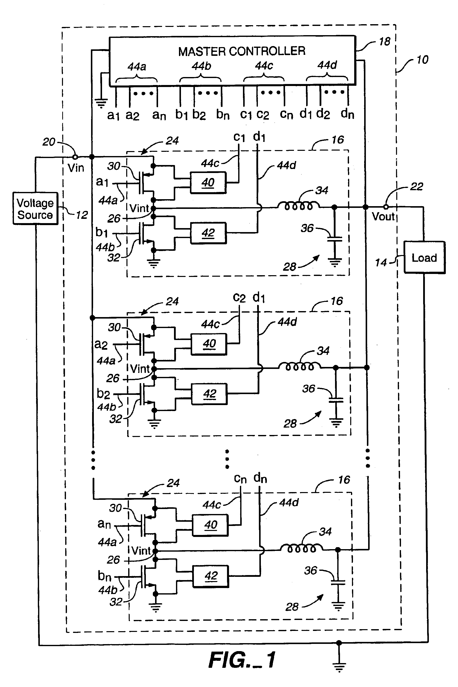
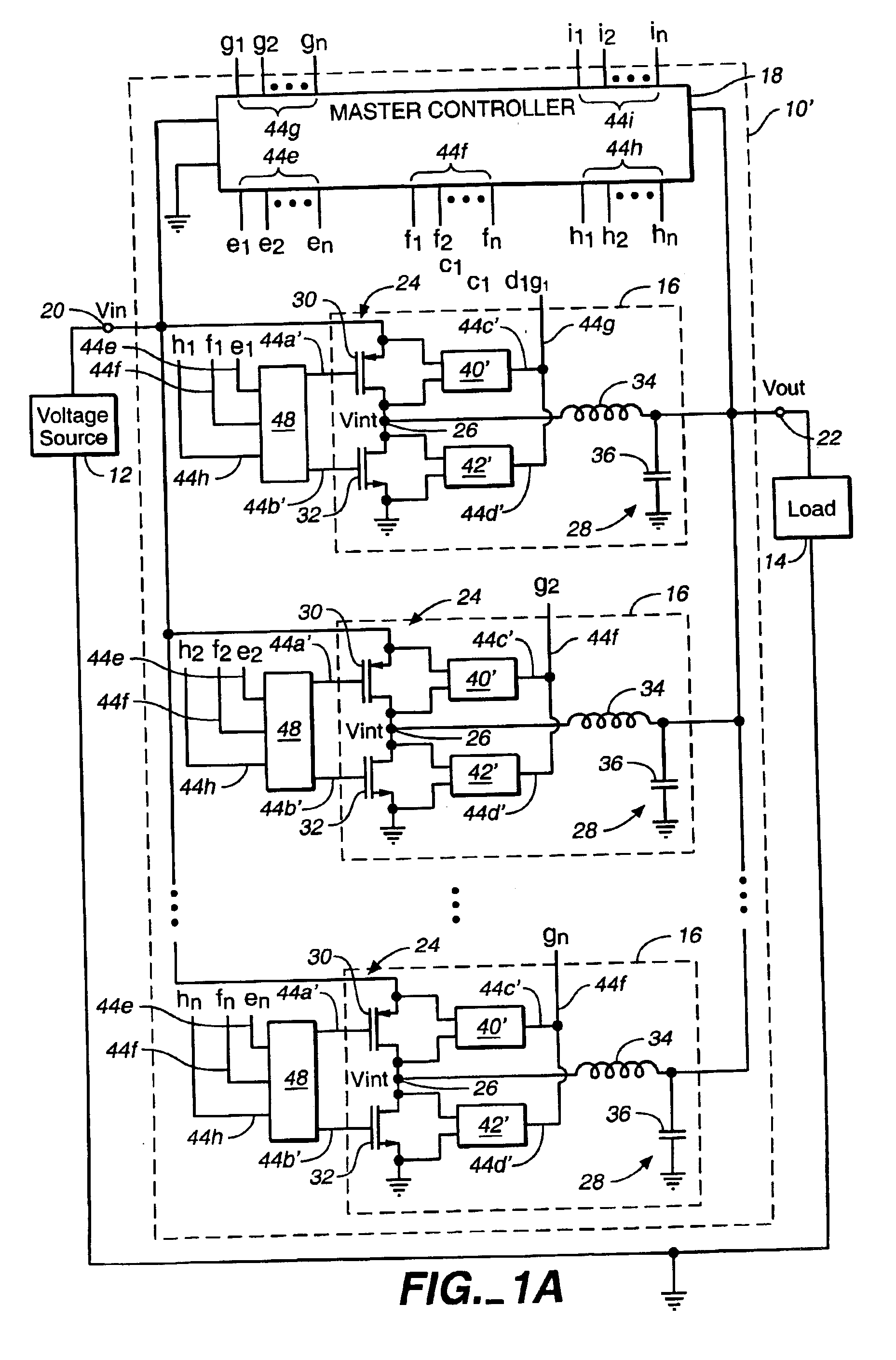
Referring to FIG. 1, a switching regulator 10 is coupled to an unregulated DC input voltage source 12, such as a battery, by an input terminal 20. The switching regulator 10 is also coupled to a load 14, such as an integrated circuit, by an output terminal 22. The load 14 typically has an expected nominal voltage Vnom and a voltage tolerance ΔVnom. A typical nominal voltage Vnom for a microprocessor chip is about 1.0 to 5.0 volts, e.g., about 1.2 to 1.8 volts, and a typical voltage tolerance ΔVnom is + / −6% of the nominal voltage Vnom, i.e., about 80 mV for a 1.2 volt nominal voltage. The switching regulator 10 serves as a DC-to-DC converter between the input terminal 20 and the output terminal 22. The switching regulator 10 includes one or more slaves 16 for converting an input voltage Vin at the input terminal 20 to an output voltage Vout at the output terminal 22 which is within the tolerance ΔVnom of the nominal voltage Vnom, and a master controller 18 for controlling the operati...


PUM


Abstract

A digitally implemented voltage regulator having including a plurality of slaves coupled in parallel. Each slave includes a switching circuit that intermittently couples an input terminal and an output terminal of the voltage regulator in response to a digital control signal for the corresponding slave. A current sensor in each slave generates a digital first feedback signal derived from the current passing through the corresponding switching circuit. A digital controller receives and uses the digital feedback signals from the plurality of slaves to generate a digital control signal for each slave. The digital controller operates active slaves of the plurality of slaves at determined phase offsets to minimize voltage ripple and maintain the output voltage at the output terminal at a substantially constant level.

Description

BACKGROUNDThe present invention relates generally to voltage regulators, and more particularly to control systems for switching voltage regulators.Voltage regulators, such as DC to DC converters, are used to provide stable voltage sources for electronic systems. Efficient DC to DC converters are particularly needed for battery management in low power devices, such as laptop notebooks and cellular phones. Switching voltage regulators (or more simply “switching regulators”) are known to be an efficient type of DC to DC converter. A switching regulator generates an output voltage by converting an input DC voltage into a high frequency voltage, and filtering the high frequency voltage to generate the output DC voltage. Typically, the switching regulator includes a switch for alternately coupling and de-coupling an unregulated input DC voltage source, such as a battery, to a load, such as an integrated circuit. An output filter, typically including an inductor and a capacitor, is coupled...

Claims


Application Information

Patent Timeline
IPC IPC(8): H02M3/158H02M3/04H02M3/157
CPCH02M3/1584H02M3/157
Inventor BURSTEIN, ANDREW J.LIDSKY, DAVID B.STRATAKOS, ANTHONYSULLIVAN, CHARLIECLARK, WILLIAM
Owner VOLTERRA SEMICONDUCTOR
Learn More