DC power source device and inverter device and air-conditioner using these
A technology of a DC power supply and a driving device, which is applied in the conversion device of output power, the conversion of AC power input into DC power output, and the conversion of irreversible AC power input into DC power output, etc., can solve the obstacles to the miniaturization and smoothness of DC power supply devices Problems such as the increase in the capacitance of the capacitor
- Summary
- Abstract
- Description
- Claims
- Application Information
AI Technical Summary
Problems solved by technology
Method used
Image
Examples
Embodiment approach 1
[0045] 1. Structure
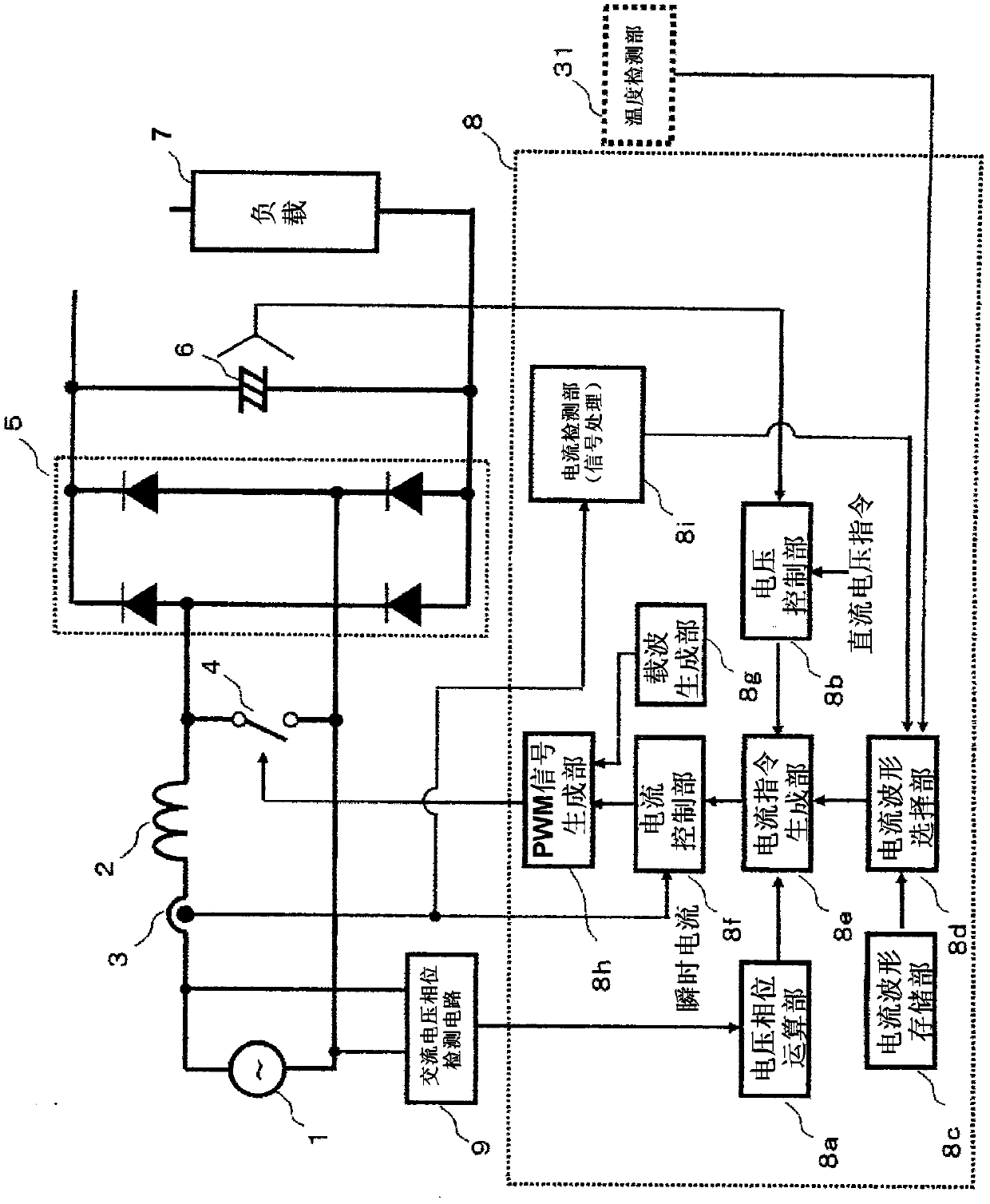
[0046] figure 1 It is a diagram showing the circuit configuration of the DC power supply device according to Embodiment 1.
[0047] like figure 1 As shown, the DC power supply device according to Embodiment 1 includes a reactor 2 , an input current detection unit 3 , a switch mechanism 4 , a rectifier circuit 5 , and a smoothing capacitor 6 , and supplies a DC voltage to a load 7 .
[0048] Reactor 2 is connected to one end of AC power supply 1 .
[0049] The input current detection unit 3 detects the current flowing through the reactor 2 .
[0050] The switch mechanism 4 short-circuits and opens the AC power supply 1 via the reactor 2 . The switch mechanism 4 is only required to be bidirectional, and is constituted by, for example, a combined circuit of one diode bridge and one IGBT, or two power MOSFETs connected in opposite directions.
[0051] The AC input end of the rectifier circuit 5 is connected to both ends of the switch mechanism 4 .
[...
Embodiment approach 2
[0091] Image 6 It is a figure which shows the structure of the inverter drive apparatus of 2nd Embodiment.
[0092] like Image 6 As shown, the inverter driving device of the second embodiment has the same figure 1 The shown DC power supply device has the same configuration as the DC power supply device of Embodiment 1, and includes a motor 10 , an inverter 11 for driving the motor 10 , and an inverter control unit 12 for driving the inverter 11 as a load.
[0093] The DC power supply device of the inverter drive device according to Embodiment 2 has the same configuration as the DC power supply device according to Embodiment 1, so description thereof will be omitted, and only the parts different from the DC power supply device according to Embodiment 1 will be described.
[0094] The inverter drive device according to Embodiment 2 further includes a current limit value storage unit 13 , a current limit value selection unit 14 , and a comparison unit 15 .
[0095] The curr...
Embodiment approach 3
[0112] Figure 8A and Figure 9A It is a diagram showing a configuration example of the AC voltage phase detection circuit 9 of the DC power supply device (inverter drive device) according to the third embodiment. These AC voltage phase detection circuits 9 and a voltage phase calculation unit 8 a described later constitute a voltage phase detection unit of the AC power supply 1 .
[0113] Figure 8A It is a figure which shows an example of the structure of the circuit which can distinguish the positive and negative voltage phases of the AC power supply 1. like Figure 8B As shown, in this circuit configuration, the value of the output signal (binary signal) generated by the AC voltage phase detection circuit 9 changes when the voltage peak value of the AC power source 1 is equal to the predetermined voltage V1. That is, the value of the binary signal changes only in the phase of the half-wave side of the AC power supply 1 . Thereby, it is possible to determine whether th...
PUM
 Abstract
Description
Claims
Application Information
 - R&D
- Intellectual Property
- Life Sciences
- Materials
- Tech Scout
- Unparalleled Data Quality
- Higher Quality Content
- 60% Fewer Hallucinations
Browse by: Latest US Patents, China's latest patents, Technical Efficacy Thesaurus, Application Domain, Technology Topic, Popular Technical Reports.
© 2025 PatSnap. All rights reserved.Legal|Privacy policy|Modern Slavery Act Transparency Statement|Sitemap|About US| Contact US: help@patsnap.com


