
Methods and systems for selectively connecting and disconnecting conductors in a fabric

a technology of selective connection and disconnection, applied in the field of forming, can solve the problems of increasing dc resistance, affecting the ac and dc characteristics of the connection point, and affecting the uniformity of the resistance between the contact point, so as to achieve the effect of improving both ac and dc characteristics

Inactive Publication Date: 2005-02-08
NORTH CAROLINA STATE UNIV
View PDF62 Cites 65 Cited by
  • Summary
  • Abstract
  • Description
  • Claims
  • Application Information

AI Technical Summary

Benefits of technology

The present invention includes methods and systems for selectively connecting and disconnecting conductors in a fabric. According to one aspect of the invention, first and second conductors are woven into a fabric such that the first and second conductors intersect at a crossover point. Next, heat and / or electrical energy is applied to the first and second conductors at the crossover point. The application of heat and / or electrical energy bonds the conductors at the crossover point and thereby improves both AC and DC characteristics.
Because conductive fibers can be selectively connected and disconnected in a flexible substrate, such as a fabric, the footprint of the circuit board is reduced. For example, a fabric with interconnected conductive fibers can be rolled up and / or folded to increase electrical component density.
It is another object of the invention to provide methods and systems for selectively connecting and disconnecting conductors in a fabric that improve AC and DC signal characteristics.
It is another object of the invention to provide methods and systems for selectively connecting and disconnecting conductors in a fabric that are easily integratable into commercial fabric production processes, such as weaving.

Problems solved by technology

One problem with conventional fabric-based electric circuits is that the electrical resistance of connection points in a fabric varies from one connection point to another.
As a result, uniform resistance between contact points cannot be achieved.
In addition, reduced contact between conductors at contact points increases DC resistance and produces undesirable AC characteristics, such as parasitic capacitance and inductance.

Method used


Image

  • Methods and systems for selectively connecting and disconnecting conductors in a fabric
  • Methods and systems for selectively connecting and disconnecting conductors in a fabric
  • Methods and systems for selectively connecting and disconnecting conductors in a fabric

Examples


Embodiment Construction

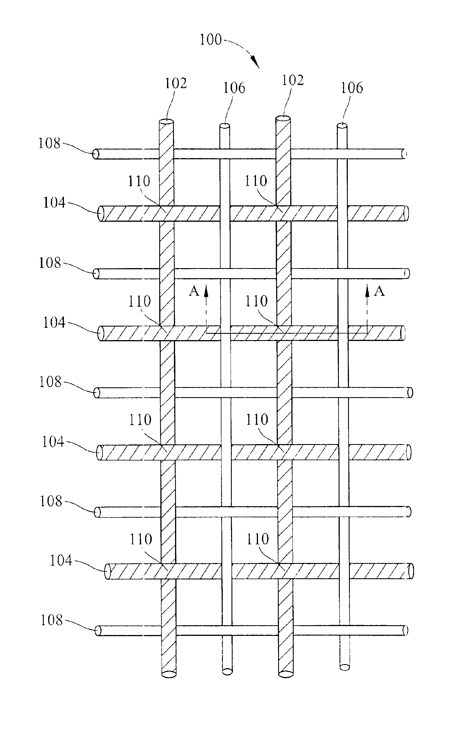
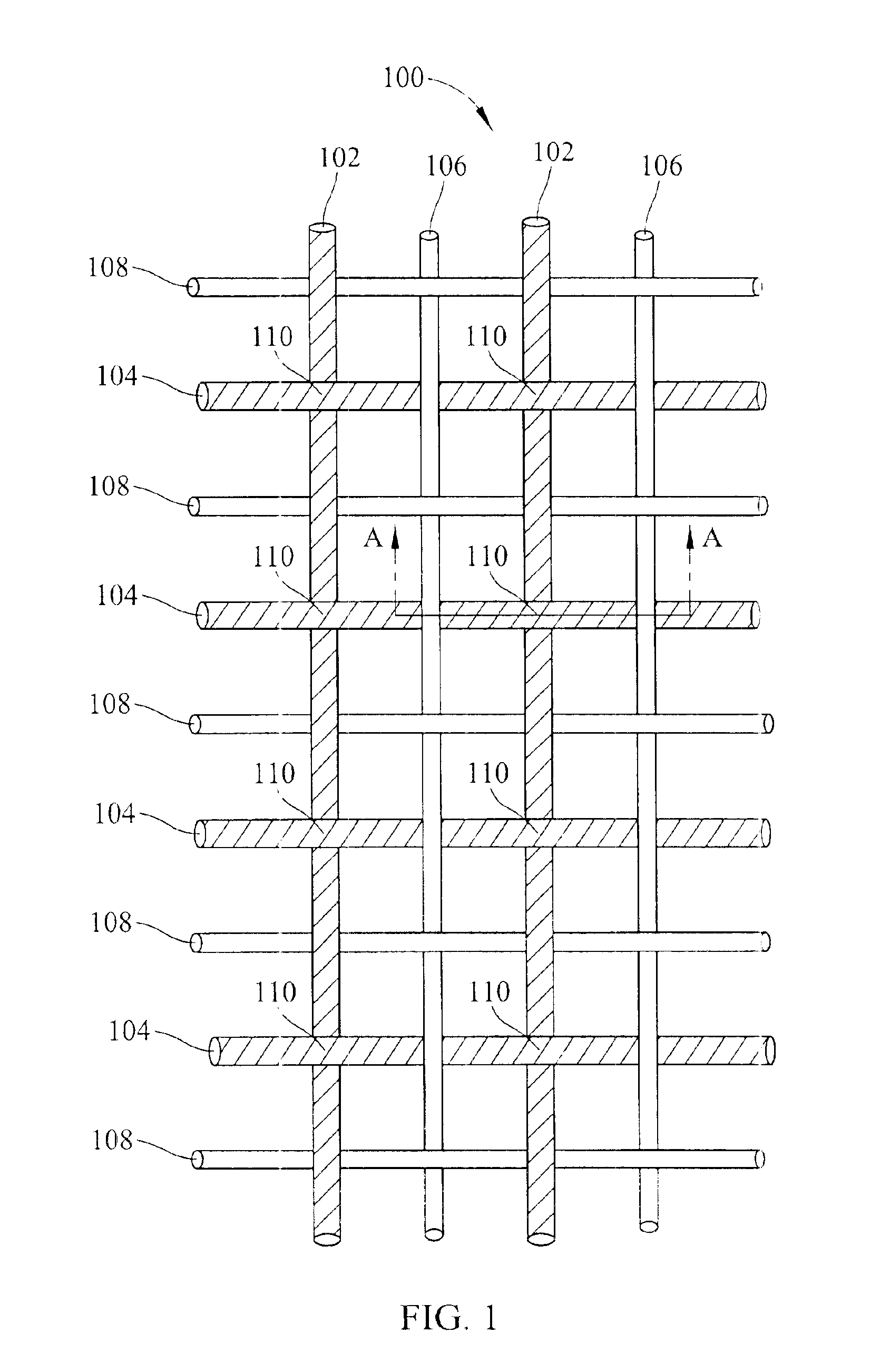
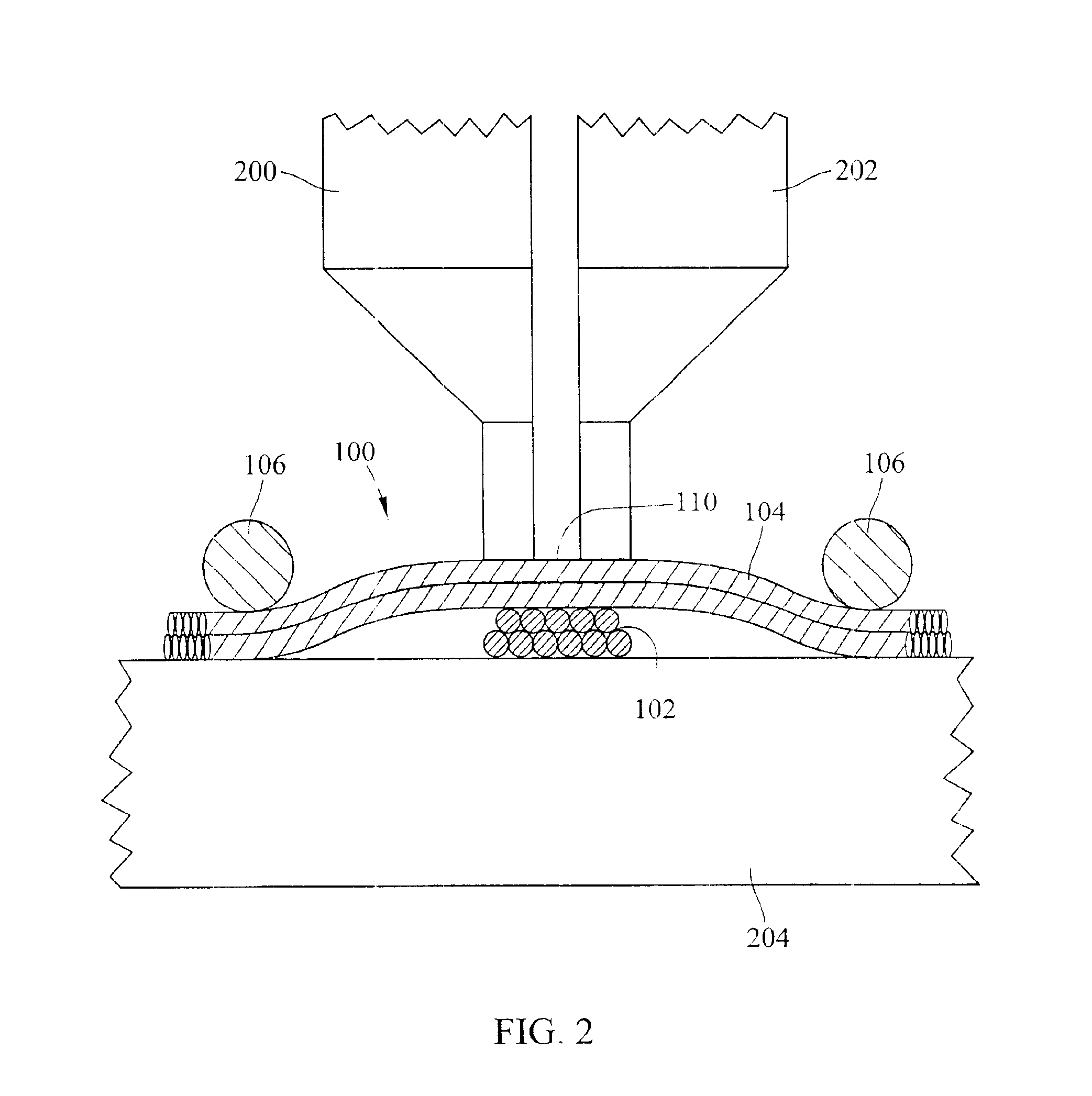
FIG. 1 illustrates a fabric including conductive and non-conductive fibers according to an embodiment of the present invention. In FIG. 1, a fabric 100 includes a plurality of conductors 102 and 104 and a plurality of non-conductive fibers 106 and 108. Conductors 102 and 104 may be any type of material capable of conducting an electrical signal. For example, conductors 102 and 104 may be metallic conductors, such as copper, gold, steel, aluminum, silver, or iron. Alternatively, conductors 102 and 104 may be conductive polymers or polymers with conductive coating. Conductors 102 and 104 may be single-wire conductors, coaxial conductors, mono or multi-filament conductive yarn constructions, twisted pair conductors, braided conductors, or any other form of conductor, depending on desired AC and DC characteristics. Non-conductive fibers 106 and 108 may be any type of non-conductive fiber suitable for forming a fabric. For example, non-conductive fibers 106 and 108 may each comprise poly...


PUM

PropertyMeasurementUnit
electrical energyaaaaaaaaaa
metallicaaaaaaaaaa
conductiveaaaaaaaaaa

Abstract

Methods and systems for selectively connecting and disconnecting conductors in a fabric are disclosed. First and second conductors are integrated into a fabric such that the conductors intersect at a crossover point. The conductors are bonded to each other at the crossover point to improve AC and DC characteristics. Disconnect areas may be provided near the crossover point to allow selective disconnection of the conductors from the crossover point.

Description

TECHNICAL FIELDThe present invention relates to methods and systems for forming fabric-based electric circuits and / or circuit boards. More particularly, the present invention relates to methods and systems for selectively connecting and disconnecting conductors in a fabric.BACKGROUND ARTIn order to increase the density and flexibility of electric circuits, electric circuits have been formed on non-rigid substrates, such as woven and non-woven fabrics. Exemplary applications for fabric-based electric circuits include communications devices, such as cellular telephones, tactile sensors, biomedical sensors, general purpose computers, etc. In addition, flexible electric circuits, such as fabric-based watches, can be integrated into articles of clothing.One problem with conventional fabric-based electric circuits is that the electrical resistance of connection points in a fabric varies from one connection point to another. For example, if conductors are woven into a fabric as warp yarns ...

Claims


Application Information

Patent Timeline
Patent Type & Authority Patents(United States)
IPC IPC(8): B01D39/08H05K7/02H05K7/06H05K1/00
CPCB01D39/083B01D39/086H05K1/0289H05K7/06B01D2239/0208B01D2239/0216B01D2239/0241B01D2239/0636Y10T428/2481B01D2239/086H05K1/038Y10T428/24826B01D2239/069Y10T442/339Y10T442/3976Y10T442/475Y10T442/655Y10T442/696
Inventor DHAWAN, ANUJGHOSH, TUSHAR KANTIMUTH, JOHNSEYAM, ABDELFATTAH
Owner NORTH CAROLINA STATE UNIV
Learn More