Waveguide antenna apparatus provided with rectangular waveguide and array antenna apparatus employing the waveguide antenna apparatus

a waveguide antenna and rectangular waveguide technology, applied in the direction of slot antennas, antennas, basic electric elements, etc., can solve the problems of ineffective radiation of electromagnetic waves, restriction in the installation place of the antenna apparatus, and the structure of the antenna apparatus of the first prior art, etc., to achieve simple design

Inactive Publication Date: 2005-02-01
PANASONIC CORP
View PDF8 Cites 7 Cited by
  • Summary
  • Abstract
  • Description
  • Claims
  • Application Information

AI Technical Summary

Benefits of technology

An essential object of the present invention is to solve the above-mentioned problems and provide a compact and light-weight antenna apparatus capable of obtaining a directivity having an extremely strong main beam in one direction with a simple design.

Problems solved by technology

However, the first prior art antenna apparatus shown in FIG. 59 has the following problems.
The first prior art antenna apparatus, which is suitable for an elongated coverage area of a corridor or the like, can not effectively radiate an electromagnetic wave in the case where the antenna apparatus is allowed to be installed only at the end of the coverage area such as a place near an indoor wall or window.
That is, there has been a restriction in the installation place of the antenna apparatus.
Therefore, the structure of the antenna apparatus of the first prior art, which has not been able to effectively utilize the electromagnetic wave radiated from the antenna apparatus in the case where the antenna apparatus has been allowed to be installed only at the end of the coverage area, has been inevitably regarded as improper.
Moreover, the antenna apparatus disclosed in the publication of the second prior art has the following problems.
Therefore, the structure of the second prior art, which has had a tendency to attract human attention because of its incapability of having a low-profile configuration, has been inevitably regarded as improper.

Method used


Image

  • Waveguide antenna apparatus provided with rectangular waveguide and array antenna apparatus employing the waveguide antenna apparatus
  • Waveguide antenna apparatus provided with rectangular waveguide and array antenna apparatus employing the waveguide antenna apparatus
  • Waveguide antenna apparatus provided with rectangular waveguide and array antenna apparatus employing the waveguide antenna apparatus

Examples


first preferred embodiment

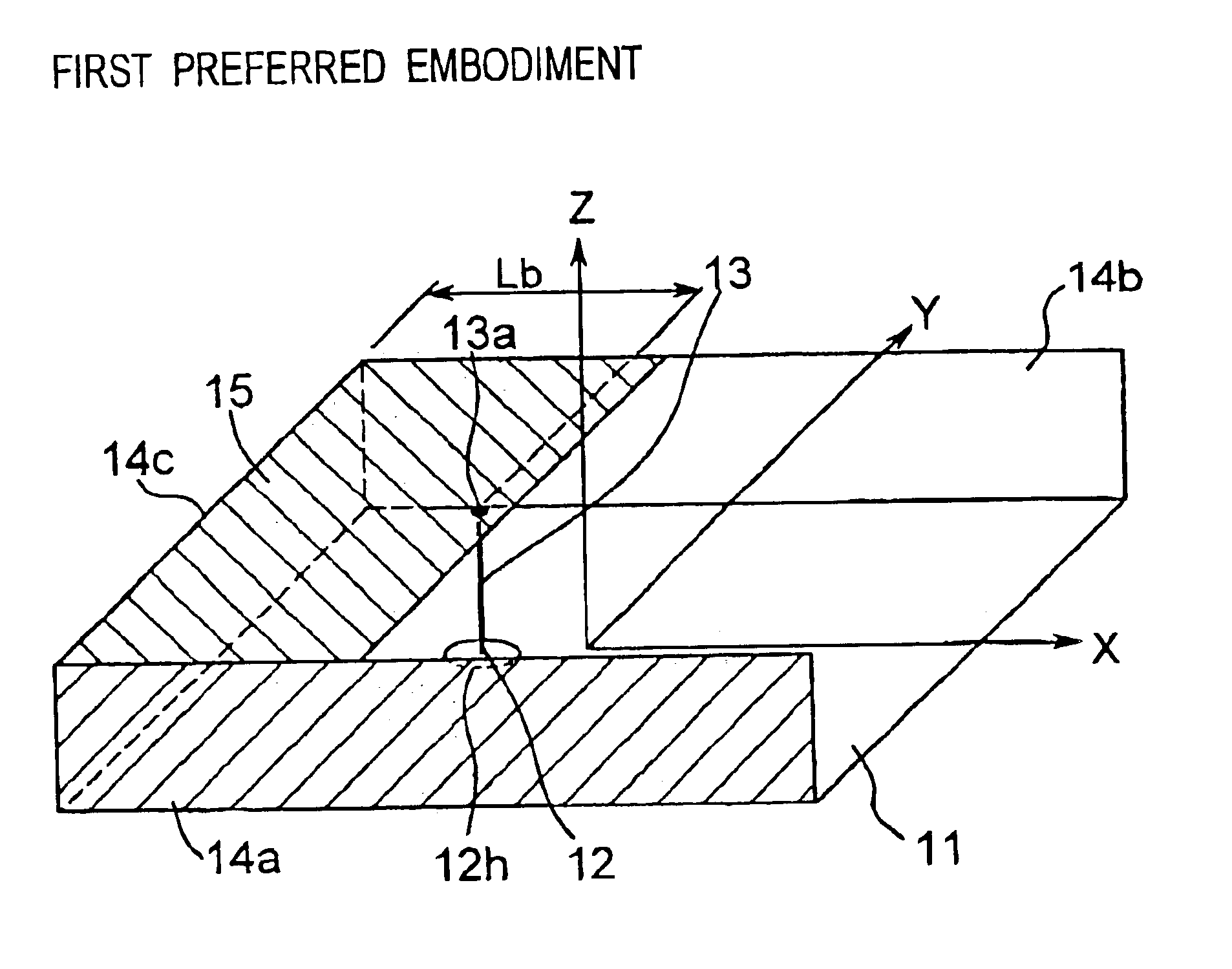
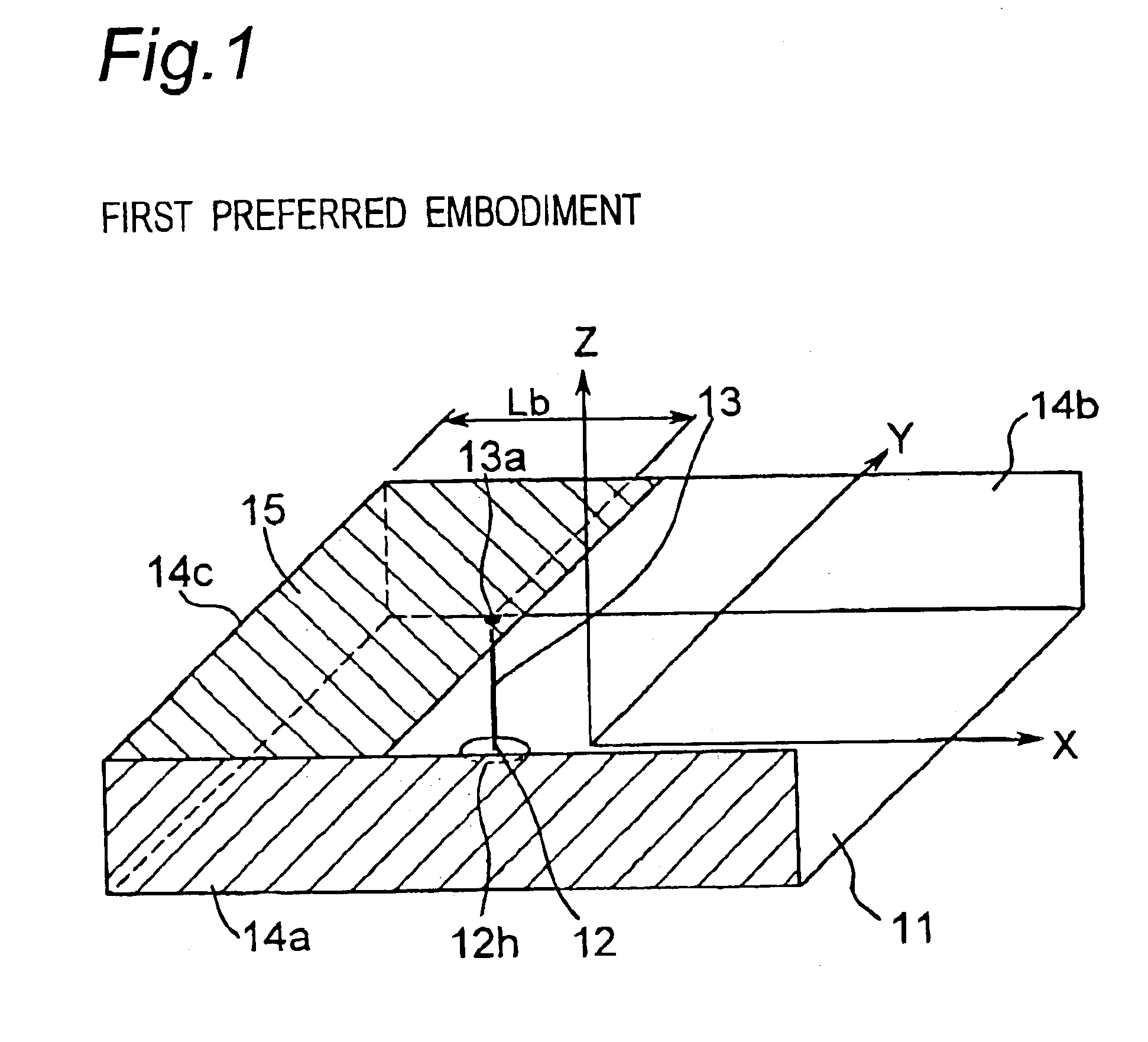
FIG. 1 is a perspective view showing a configuration of an open-ended waveguide antenna apparatus according to the first preferred embodiment of the present invention.

Referring to FIG. 1, the open-ended waveguide antenna apparatus of the first preferred embodiment includes a rectangular waveguide formed by including the following:(a) a rectangular grounding conductor 11 located on the bottom surface on the X-Y plane;(b) a rectangular ceiling conductor 15 arranged so as to oppose to the grounding conductor 11 on the top surface of the open-ended waveguide antenna apparatus; and(c) rectangular side surface conductors 14a and 14b that join the grounding conductor 11 with the ceiling conductor 15 and are opposed to each other.

One end portion of the rectangular waveguide is short-circuited by being terminated so as to be sealed with a rectangular terminating conductor 14c, while another end of the rectangular waveguide is opened because the ceiling conductor 15 is partially removed and i...

second preferred embodiment

FIG. 16 is a perspective view showing a configuration of a slit radiation type waveguide antenna apparatus according to the second preferred embodiment of the present invention.

Referring to FIG. 16, the slit radiation type waveguide antenna apparatus of the present preferred embodiment includes a rectangular waveguide formed by including the following:(a) a square grounding conductor 11 located on the bottom surface on the X-Y plane;(b) rectangular ceiling conductors 15a and 15b arranged so as to oppose the grounding conductor 11 on the top surface of the slit radiation type waveguide antenna apparatus (hereinafter referred to as an antenna ceiling portion); and(c) rectangular side surface conductors 14a and 14b that join the grounding conductor 11 with the ceiling conductors 15a and 15b.

Two terminal portions in the longitudinal direction of the rectangular waveguide are terminated and short-circuited by rectangular terminating conductors 14c and 14d, respectively. The grounding co...

third preferred embodiment

FIG. 28 is a perspective view showing a configuration of an open-ended waveguide antenna apparatus with a slit 20 according to the third preferred embodiment of the present invention.

Referring to FIG. 28, the open-ended waveguide antenna apparatus with the slit 20 is different from the open-ended waveguide antenna apparatus of FIG. 1 in the following points:

(1) In the antenna ceiling portion, one slit 20, which has a longitudinal direction parallel to the Y-axis and has a width sufficiently smaller than a quarter wavelength of the guide wavelength, is provided between the ceiling conductors 15a and 15b. The ceiling conductor 15a is located on the side of the opened end of the waveguide, and the ceiling conductor 15b is located on the side of the short-circuited end of the waveguide with interposition of the slit 20.

(2) The side conductor 14a has a length smaller than that of the side surface conductor 14a of FIG. 1 and has the same length as that of the ceiling conductor 15 in the X...


PUM


Abstract

A waveguide antenna apparatus is provided including a rectangular waveguide having one end short-circuited by a terminating conductor and another end opened. The rectangular waveguide includes a grounding conductor and a ceiling conductor opposed to each other, and includes two side surface conductors joining the grounding conductor with the ceiling conductor and being opposed to each other. An antenna element has one end and another end, where one end thereof is connected with a position in the ceiling conductor in a vicinity of opened another end of the rectangular waveguide, and another end thereof is connected with a feeding portion located in the grounding conductor. The ceiling conductor includes a removed portion on the side of opened another end of the rectangular waveguide. Then an electromagnetic wave of a fed radio signal is radiated from the removed portion and opened another end of the rectangular waveguide.

Description

BACKGROUND OF THE INVENTION1. Field of the InventionThe present invention relates to a waveguide antenna apparatus and an array antenna apparatus that employs the waveguide antenna apparatus, and in particular, to a waveguide antenna apparatus constituted by including a rectangular waveguide and an array antenna apparatus that employs the waveguide antenna apparatus.2. Description of the Related ArtFIG. 59 is a perspective view showing a configuration of a prior art antenna apparatus (hereinafter referred to as a first prior art) that has a bi-directional pattern on the horizontal plane, and FIGS. 60A and 60B are graphs showing radiation directivity patterns of the antenna apparatus of FIG. 59. In this case, FIG. 60A is a graph showing a radiation directivity pattern on the X-Y plane, and FIG. 60B is a graph showing a radiation directivity pattern on the X-Z plane. In FIG. 59, reference is made to an X-Y-Z coordinates system illustrated for explanation. In this specification, the X-...

Claims


Application Information

Patent Timeline
Patent Type & Authority Patents(United States)
IPC IPC(8): H01Q13/00H01Q13/10H01Q19/00H01Q13/08H01Q13/02H01Q13/18
CPCH01Q13/02H01Q19/005H01Q13/18H01Q13/08
Inventor YAMAMOTO, ATSUSHIIWAI, HIROSHIOGAWA, KOICHI
Owner PANASONIC CORP
Why Eureka
Try Eureka