Compact wavelength filter using optical birefringence and reflective elements

a technology of optical birefringence and reflective elements, applied in the field of optical wavelength filters, can solve the problems of inability to meet the needs of polarizing elements, and inability to separate wavelengths, so as to reduce the polarization dispersion, and reduce the polarization

Inactive Publication Date: 2005-01-25
EZCONN
View PDF97 Cites 12 Cited by
  • Summary
  • Abstract
  • Description
  • Claims
  • Application Information

AI Technical Summary

Benefits of technology

her separates the wavelengths. One advantage of the present invention is that the polarization-based wavelength multiplexing / demultiplexing device has good peak flatness and low crosstalk, and permits separation of closely spaced wavelengths (e.g., 50 GHz spacing). The subsequent devices in the cascade can be based on a number of technologies including arrayed waveguide technology, fused biconical taper technology, diffraction grating technology, fiber Bragg grating technology, interference filter, or can also be polarization-based devices. The subsequent devices are used to separate channels which have been formed into subgroups by the polarization-based wavelength multiplexing / demultiplexing device.
In a preferred embodiment the polarization-based wavelength multiplexer / demultiplexer creates two subsets, one subset containing the odd channels from the input channels, the other subset containing the even channels from the input channels. The second device further separates the wavelengths in the first and second subsets, resulting in a wavelength spacing at the output which is 2N times the wavelength spacing at the input of the polarization-based wavelength multiplexer / demultiplexer. In a preferred embodiment the second stage performs the subsequent demultiplexing operations. In an alternate embodiment multiple stages are used in the cascade to further separate the wavelengths and produce a single channel at the final output.
In an alternate embodiment, the polarization-based wavelength multiplexer / demultiplexer separates an upper band from a lower band. Subsequent stages are used to further separate the channels.
When a large number of channels are present, the polarization-based multiplexer / demultiplexer can be utilized to separate the channels into groups, and subsequent stages can be used to continue the multiplexing / demultiplexing process. In a preferred embodiment, when used as a demultiplexer, the present invention separates an input signal into two groups of channels, the even channels and the odd channels. A subsequent stage based on arrayed waveguide (AWG) technology performs the final multiplexing, resulting in individual channels at the output.
In a preferred embodiment the polarization-based wavelength division multiplexing / demultiplexing device is based on a polarization routing device which receives an optical signal carrying multiple channels at various wavelengths, separates the signal into vertical and horizontal polarizations, converts one of the polarizations to be identical to the other polarization, and performs filtering based on the wavelength of the signal, with the polarization of the output being dependent on the wavelength. A polarization routing stage routes light to a particular output depending on its polarization, and a polarization conversion and recombination stage combines the polarizations at each output to form an output signal.
In a preferred embodiment the polarization filter is composed of calcite birefringent crystal plates. A polarization mode dispersion compensator can be utilized in the device to reduce the polarization dispersion.

Problems solved by technology

As a result, when using a traditional device in the first stage of a cascade, the transmission peaks may not have a high degree of flatness, and any drift or offset of a wavelength from its specified value may result in significant attenuation of that wavelength.
In addition, the isolation between wavelengths is frequently unsuitable with conventional interferometric devices and can result in unacceptable crosstalk between channels.

Method used


Image

  • Compact wavelength filter using optical birefringence and reflective elements
  • Compact wavelength filter using optical birefringence and reflective elements
  • Compact wavelength filter using optical birefringence and reflective elements

Examples


Embodiment Construction

In describing a preferred embodiment of the invention illustrated in the drawings, specific terminology will be used for the sake of clarity. However, the invention is not intended to be limited to the specific terms so selected, and it is to be understood that each specific term includes all technical equivalents which operate in a similar manner to accomplish a similar purpose.

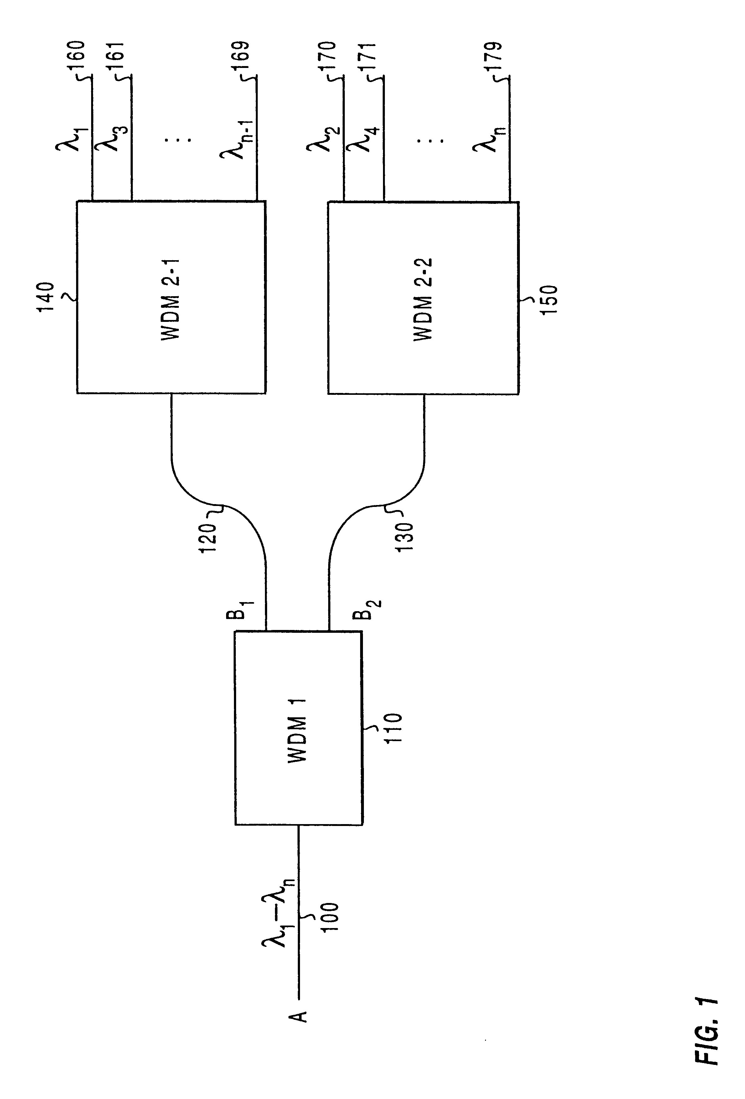
When used herein, the term multiplexer / demultiplexer refers to a device which can be used to either combine or separate wavelengths. However, such a definition does not preclude the use of the device for one function only. In addition, nonreciprocal elements can be added, precluding use of the device for one of the functions of multiplexing or demultiplexing, although the features and functionality of multiplexer / demultiplexer remain the same in the direction of use.

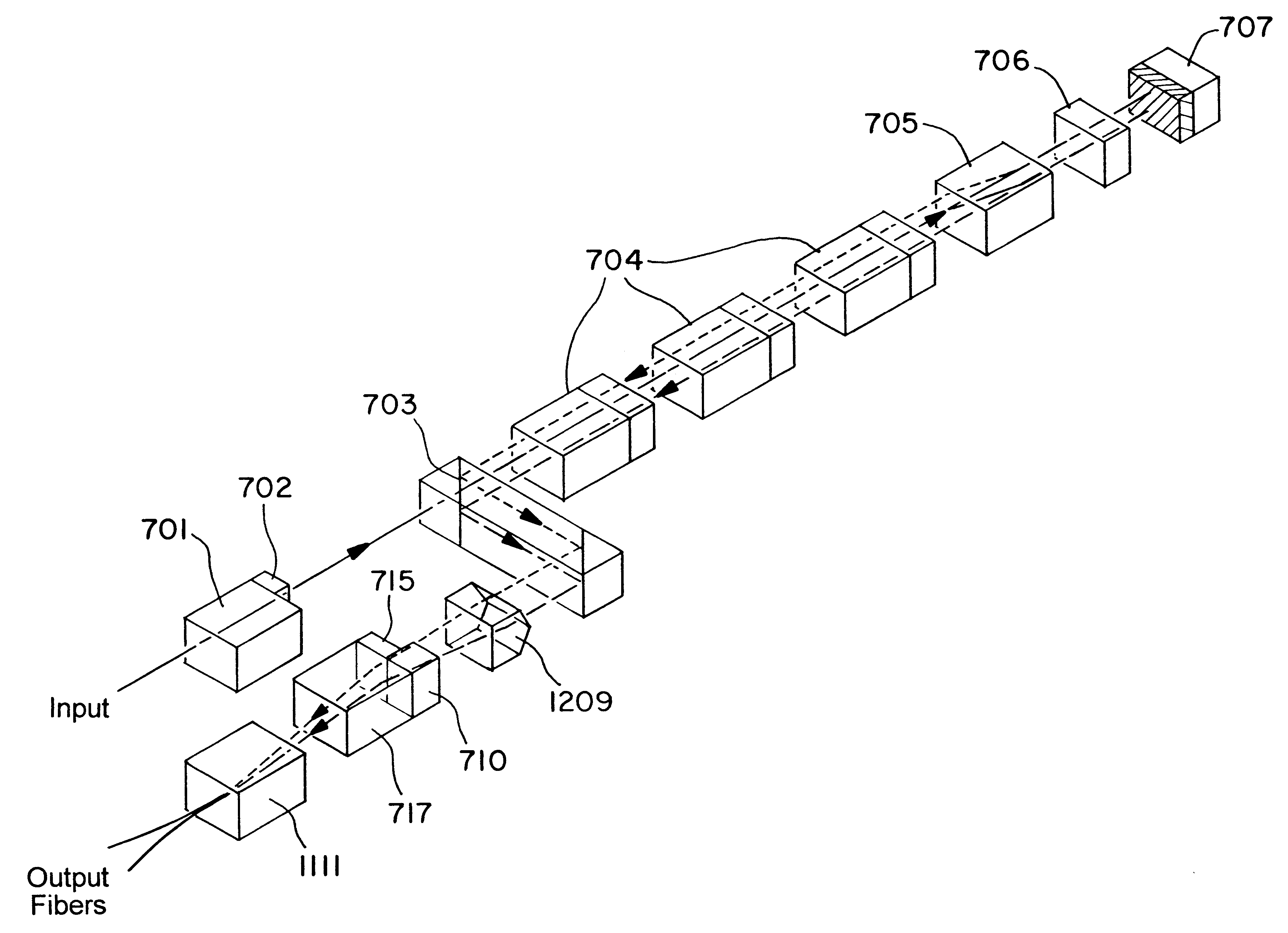
When used in a cascade, the term first stage refers to the first stage of the cascade in a demultiplexing configuration, where closely spaced wa...


PUM

PropertyMeasurementUnit
flatnessaaaaaaaaaa
optical transmission functionaaaaaaaaaa
optical pathaaaaaaaaaa

Abstract

A wavelength division multiplexing/demultiplexing device is presented utilizing a polarization-based filter to separate odd and even wavelengths, or upper and lower channels of an input optical signal. The wavelength filter first converts the input signal to a predetermined polarization. A series of birefringent waveplates provide a polarization-dependent optical transmission function such that the polarized beam is decomposed into a first beam component carrying the first spectral band at a first polarization and a second beam component carrying the second spectral band at a second, orthogonal polarization. A beam displacer spatially separates the beam components into a pair of orthogonally-polarized beams. A quarter-wave plate converts these orthogonally-polarized beams into a pair of circularly-polarized beams, which are reflected by a mirror back along parallel optical paths through the quarter-wave plate, beam displacer, and waveplates. In the return pass, the quarter-wave plate converts the reflected circularly-polarized beams into two orthogonally-polarized beams having polarizations that are rotated by 90 degrees from those in the forward pass. The waveplates further purify the spectral characteristics of the reflected beams and maintain the polarization of one of the reflected beams, while rotating the polarization of the other reflected beam by 90 degrees so that both reflected beams have substantially the same polarization. A routing element directs one of the reflected beams exiting the waveplates to a first output port and the other reflected beam to a second output port.

Description

BACKGROUND OF THE INVENTION1. Field of the InventionThe present invention relates generally to the field of optical wavelength filters. More specifically, the present invention discloses a compact wavelength filter using optical birefringence and reflective elements, primarily for wavelength division demultiplexing in optical communications systems.2. Background of the InventionWavelength division multiplexing is a commonly used technique that allows the transport of multiple optical signals, each at a slightly different wavelength, on an optical fiber. The ability to carry multiple signals on a single fiber allows that fiber to carry a tremendous amount of traffic, including data, voice, and even digital video signals. As an example, the use of wavelength division multiplexing permits a long distance telephone company to carry thousands or even millions of phone conversations on one fiber. By using wavelength division multiplexing, it is possible to effectively use the fiber at mul...

Claims


Application Information

Patent Timeline
Patent Type & Authority Patents(United States)
IPC IPC(8): G02B27/10G02F1/31G02F1/29G02B6/34H04J14/02H04Q11/00H04J14/06G02B27/28
CPCG02B6/272G02B6/29302G02B6/29394G02B6/29397G02B27/1006G02B27/12G02B27/288G02F1/31H04J14/02H04Q11/0003H04Q11/0005H04Q2011/0035H04J14/06H04Q2011/0026H04Q2011/0032G02B6/278
Inventor WONG, CHARLESLIN, LEO YU-YULIU, JIAN-YU
Owner EZCONN
Why Eureka
Try Eureka