Device for determining the level of contents in a container

a technology for determining and monitoring the level of contents in containers, applied in the direction of liquid/fluent solid measurement, engine lubrication, antennas, etc., can solve the problems of transverse resonance, interfering echo signal, so strong, etc., and achieve the effect of reducing the field length, improving the directional action, and effectively increasing the apertur

Inactive Publication Date: 2005-01-25
EHNDRESS KHAUZER GMBKH KO KG
View PDF16 Cites 7 Cited by
  • Summary
  • Abstract
  • Description
  • Claims
  • Application Information

AI Technical Summary

Benefits of technology

The directional action is improved, since because of the lesser field length, the aperture is effectively increased and the directional characteristic is improved. Thus there are fewer problems from electromagnetic fields broadcast laterally into the container, which after multiple reflections in the container could cause an interfering backgr

Problems solved by technology

If that is the case, then there is the risk that the portion of the radiation that is not guided—as desired—in the direction of the surface of the contents but instead is broadcast toward the side will lead to transverse resonances (or in the case of a connection stub, to void resonances).
The interfering echo signals that this causes can become so strong that the actual useful echo si

Method used


Image

  • Device for determining the level of contents in a container
  • Device for determining the level of contents in a container
  • Device for determining the level of contents in a container

Examples


first embodiment

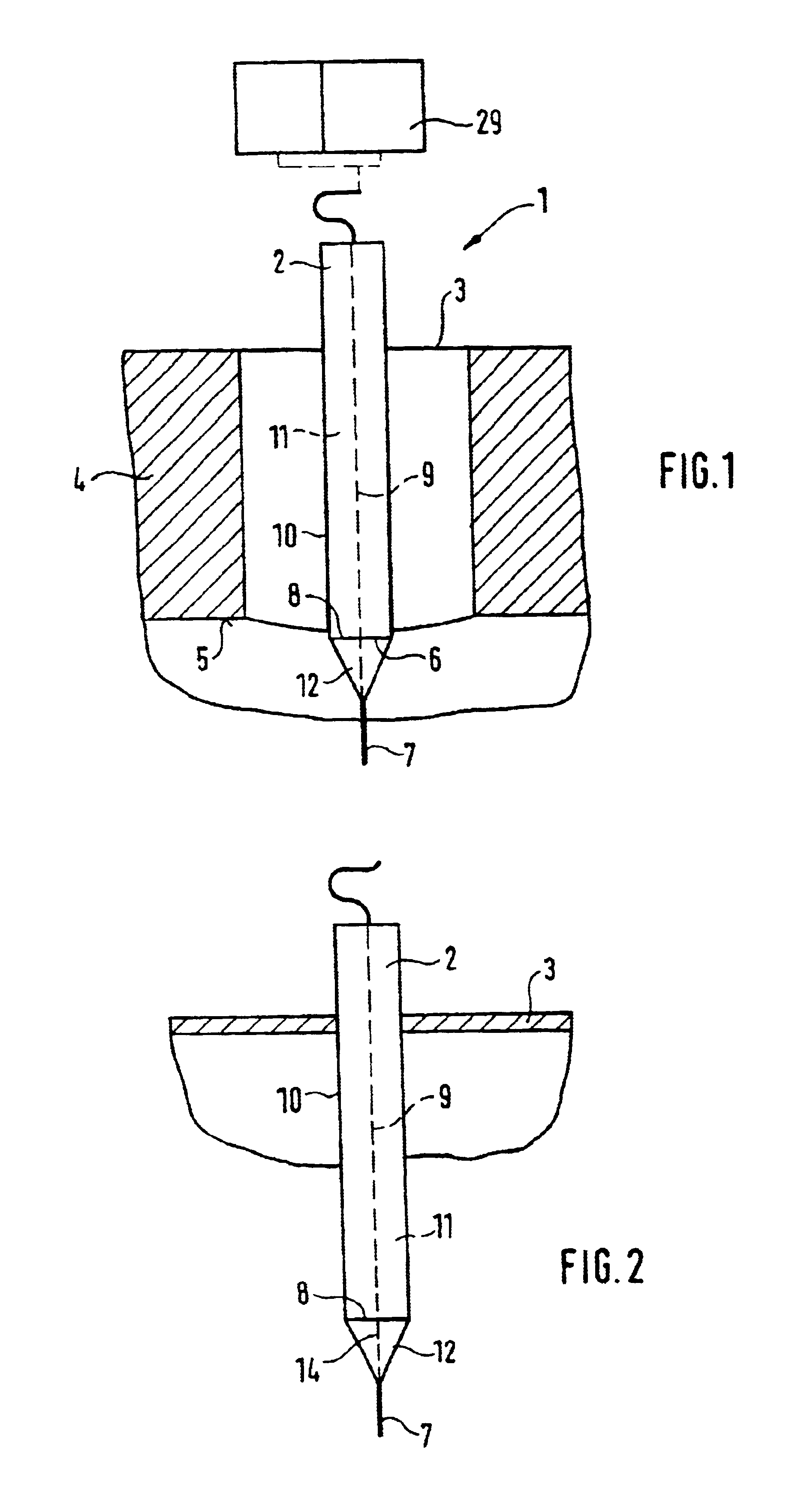
FIG. 1 is a schematic illustration of the level sensor 1 of the invention. The level sensor comprises a transceiver 29, a coaxial cable, an input unit 2, and a conductive element 7. The evaluation of the echo signals is done in an evaluation unit, not shown separately in FIG. 1.

second embodiment

In the case shown, the input unit 2 has a length that is greater than the length of the connection stub 4. The input unit 2 is disposed such that the opening 8 is in the vicinity of—in this case, below—the lower edge 5 of the connection stub 4. It is understood that the opening 8 can also be placed above the lower edge 5. Moreover, the opening 8 in the input unit 2 is dimensioned such that it is on the order of magnitude of the wavelength of the measurement signals guided by the level sensor 1. To a very great extent, the embodiment according to the invention prevents components of the measurement signals from entering the connection stub 4. Consequently, virtually no void resonances are excited, which is expressed in a considerable improvement in the measuring accuracy of the level sensor 1. In the case shown, the three-dimensional region between the inner conductor 9 and the outer conductor 10 is furthermore filled with a dielectric material 11. The advantages of this embodiment h...

third embodiment

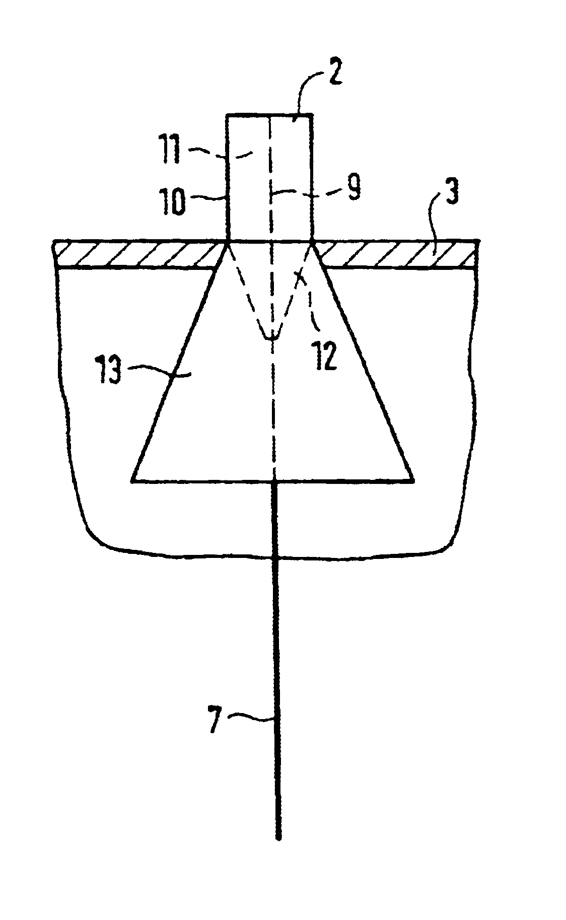
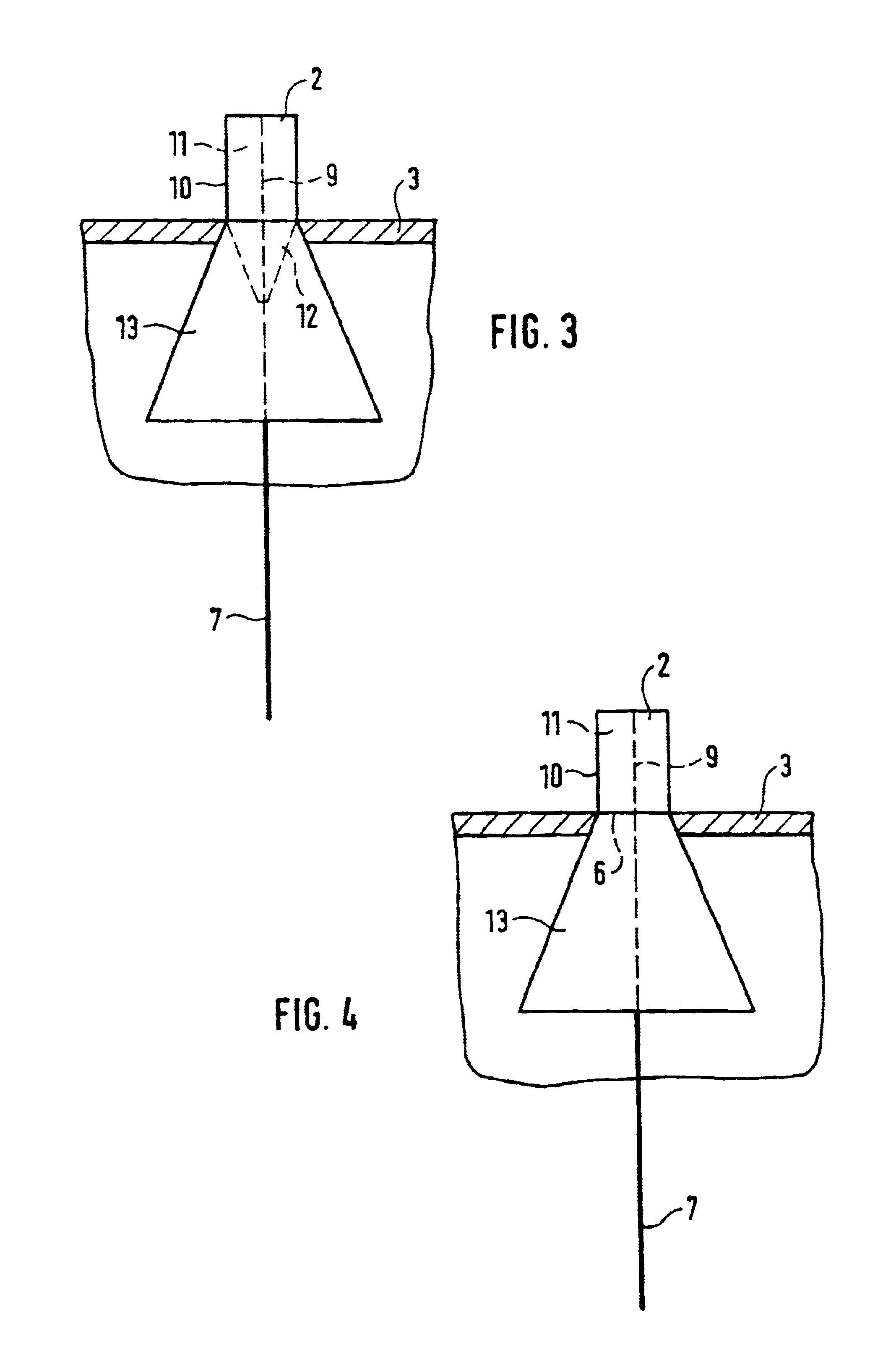
A schematic illustration of the device of the invention can be seen in FIG. 3. Here, the transition region 6 between the input unit 2 and the conductive element 7 is disposed such that it is located virtually in the plane of the container wall 3. The input unit 2 has an inner conductor 9 and an outer conductor 10. Between the two parts, a dielectric material 11 is disposed. The dielectric material 11 of the input unit 2 is tapered, approximately from the transition region 6“input unit 2—conductive element7” onward, and an upper portion of the conductive element 7 is disposed approximately in the region of the longitudinal axis of the taper 12. As the primary advantages of this embodiment, the excellent directional action, the short block distance, and the reduced risk of deposit formation can be named. To improve the directional action still further, the outer conductor 13 is widened, from the transition region 6“input unit 2—conductive element 7” onward, into a horn-shaped element ...


PUM


Abstract

A level sensor which is capable of largely eliminating the influence of structural parts and/or the formation of deposits on the measuring accuracy and on the measuring sensitivity of the level sensor. There is provided, a launching unit which has at least one length, which essentially corresponds to the distance from the container wall to the lower edge of the structural part, and which is positioned in such a manner that a transition area launching unit conductive element is located approximately in the plane of the lower edge of the structural part, with the diameter of the opening of the launching unit on the transition launching unit conductive element is in the order of magnitude of the wavelength of the high-frequency measurement signals.

Description

FIELD OF THE INVENTIONThe invention relates to a device for determining and for monitoring the level of contents in a container, in which on the container at least one structural part is provided, on which or in whose surroundings at least the sensor-associated part of the device is mounted, having a signal generating unit, which generates high-frequency measurement signals, having an input unit and a conductive element, the measurement signals being input to the conductive element via the input unit, and having a receiving / evaluating unit, which directly or indirectly via the transit time of the measurement signals, reflected from the surface or boundary face of the contents, determines the level of the contents or the location of the boundary face in the container as generically defined by the preamble to the independent claims. It is understood that the device is also suitable for determining the location of at least one boundary face between two phases of a medium or between two...

Claims


Application Information

Patent Timeline
IPC IPC(8): G01F23/284H01Q1/22H01Q19/10
CPCG01F23/284H01Q19/10H01Q1/225H01Q1/22
Inventor REIMELT, RALFSCHROTH, HERBERT
Owner EHNDRESS KHAUZER GMBKH KO KG
Why Eureka
Try Eureka