
Microelectrode machining device

a microelectrode and machining technology, applied in the direction of electrical-based machining apparatus, metal-working apparatus, manufacturing tools, etc., can solve the problems of unstable movement of the wire electrode, design restriction by the diameter of the wire, and inability to repeat the operation of the machining device, so as to increase the machining precision of the microelectrode, reduce the vibration caused by the movement, and prolong the working li

Active Publication Date: 2005-01-25
IND TECH RES INST
View PDF5 Cites 12 Cited by
  • Summary
  • Abstract
  • Description
  • Claims
  • Application Information

AI Technical Summary

Benefits of technology

The primary object of the invention is to provide a microelectrode machining device mainly consisted of a wire guide with rail, and capable of enabling a smooth movement of the wire therein so as to reduce the vibration caused by the movement and thus increase the machining precision of the microelectrode, wherein the rail is made insulating and wear-proofing materials, such that not only may the working life span thereof be prolonged, but also may the success rate of machining a microelectrode be enhanced.
The secondary object of the invention is to provide a microelectrode machining device capable of processing a microelectrode grinding procedure on an EDM machine or Micro-EDM machine, and also capable of being set up and maintained with ease by applying a modularized design thereon.
Another objective of the invention is to provide a microelectrode machining device, wherein the speed and the tension of the wire can be effectively adjusted using the mechanism of the device, such that operators of the device can adjust the tension and the speed of the wire according to the size and shape of microelectrode to be machined for obtaining an optimal machining effect.

Problems solved by technology

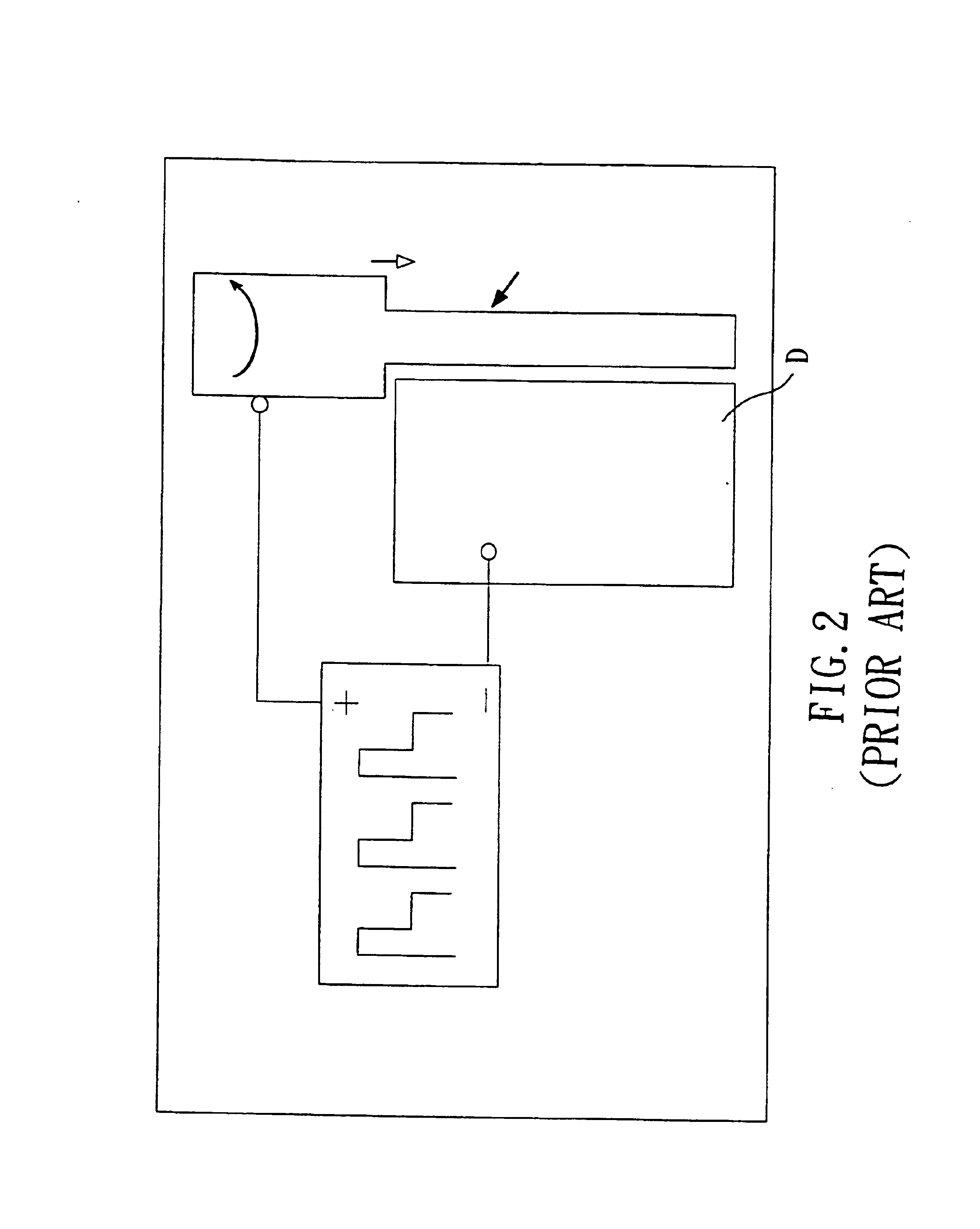
However, there are pros and cons of the two conventional methods, and the drawback of the former is that it is impossible to repetitiously compensate the wear and tear of the column electrode generated in the discharge machining process, and the shortcoming of the latter is that the two wire guides E are too widely arranged and cause an unstable movement of the wire electrode.
However, the design is restricted by the diameter of the wire, and the machined shape is also limited to cylindrical shape only that can not be used to machine a non-cylindrical-shaped electrode.
In addition, the dimension of the brass wire acted as the wire electrode is restricted, that is, the thinner the brass wire is, the more difficult it will be for machining.

Method used


Image

  • Microelectrode machining device
  • Microelectrode machining device
  • Microelectrode machining device

Examples


Embodiment Construction

For your esteemed members of reviewing committee to further understand and recognize the fulfilled functions and structural characteristics of the invention, several preferable embodiments cooperating with detailed description are presented as the follows.

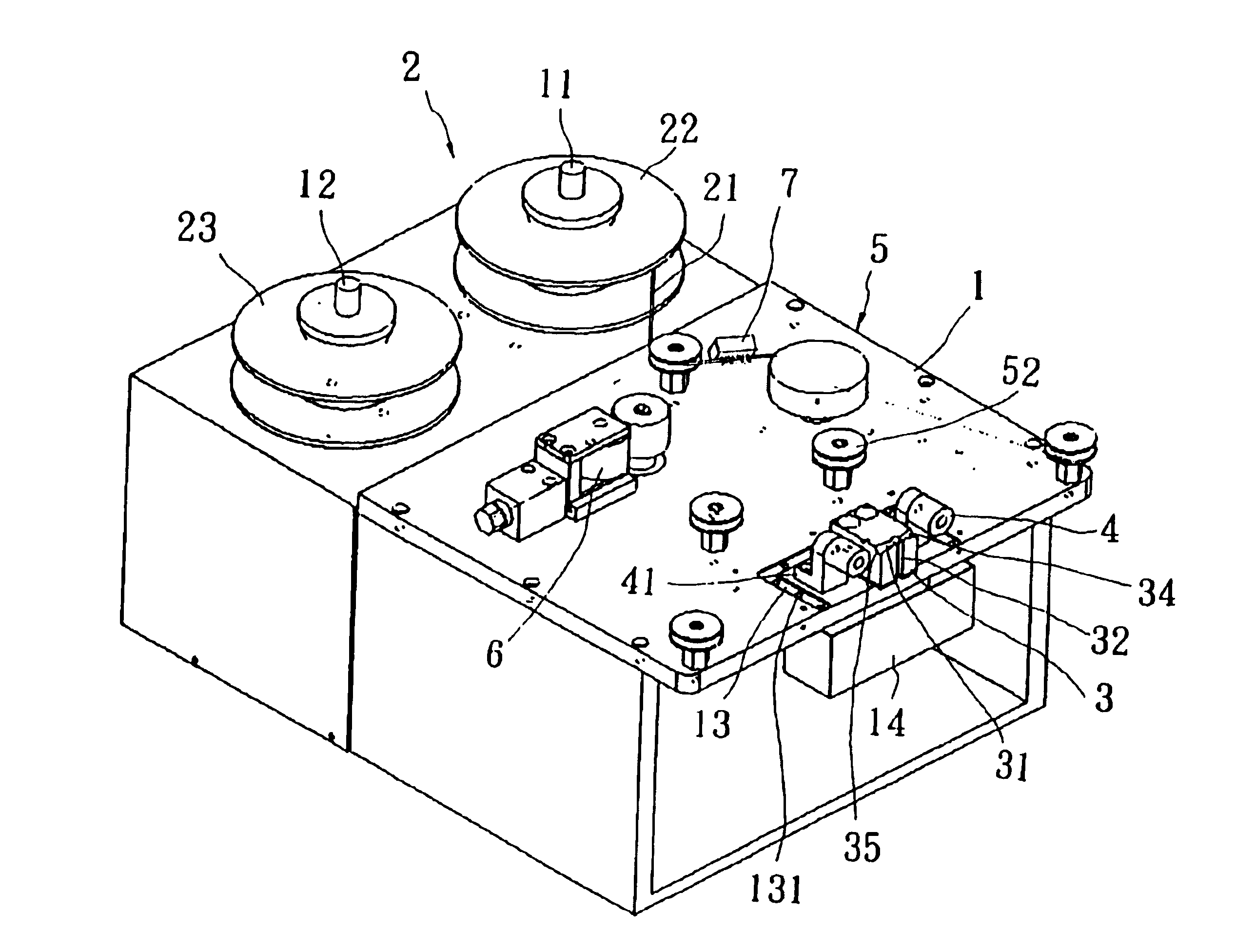
Please refer to FIG. 6 and FIG. 7, which are respectively the 3-D view and the top view of the present invention. The microelectrode machining device disclosed by the invention mainly comprises a platform 1, a wire supply mechanism 2, a wire guide 3, and two electric conductor elements 4, wherein the platform 1 can be fixed at an EDM machine (not shown in the figure), and the wire supply mechanism 2 is arranged on the platform 1 for providing the wire 21 needed in the EDM process, and the wire guide 3 disposed on the platform 1 has an arch-slide 31 arranged thereon (as shown in FIG. 8) and a groove 32 arranged at a position corresponding to the middle of the arch-slide 31 on the wire guide 3, in addition, the two electric conductor...


PUM

PropertyMeasurementUnit
altitudesaaaaaaaaaa
tensionaaaaaaaaaa
insulatingaaaaaaaaaa

Abstract

The microelectrode machining device disclosed by the invention mainly comprises a platform, a wire supply mechanism, a wire guide, and two (electric conductor)elements, wherein the platform can be fixed at an EDM machine and the wire supply mechanism is arranged on the platform for providing the wire needed in the EDM process, and the wire guide disposed on the platform has an arch-slide arranged thereon and a groove arranged at a position corresponding to the middle of the arch-slide on the wire guide, in addition, the two (electric conductor)elements are arranged on the platform to supply the power needed in the EDM process, and the two (electric conductor)elements are disposed respectively at the side of wire guide, and the altitudes of the bottom of both the wheel-shaped (electric conductor)element are lower than that of the wire exit and wire entrance of the arch-slide of the wire guide, in respective. By the design of aforementioned structure, the wire supplied by the wire supply mechanism first passes through the bottom of the (electric conductor)element, and enters the arch-slide from the wire entrance and exits the same from the wire exit, and passes again through the bottom of another (electric conductor)element. In this way, the wire is subject to a minute downward suppressing force so that the wire can travel smoothly inside the arch-slide of the wire guide.

Description

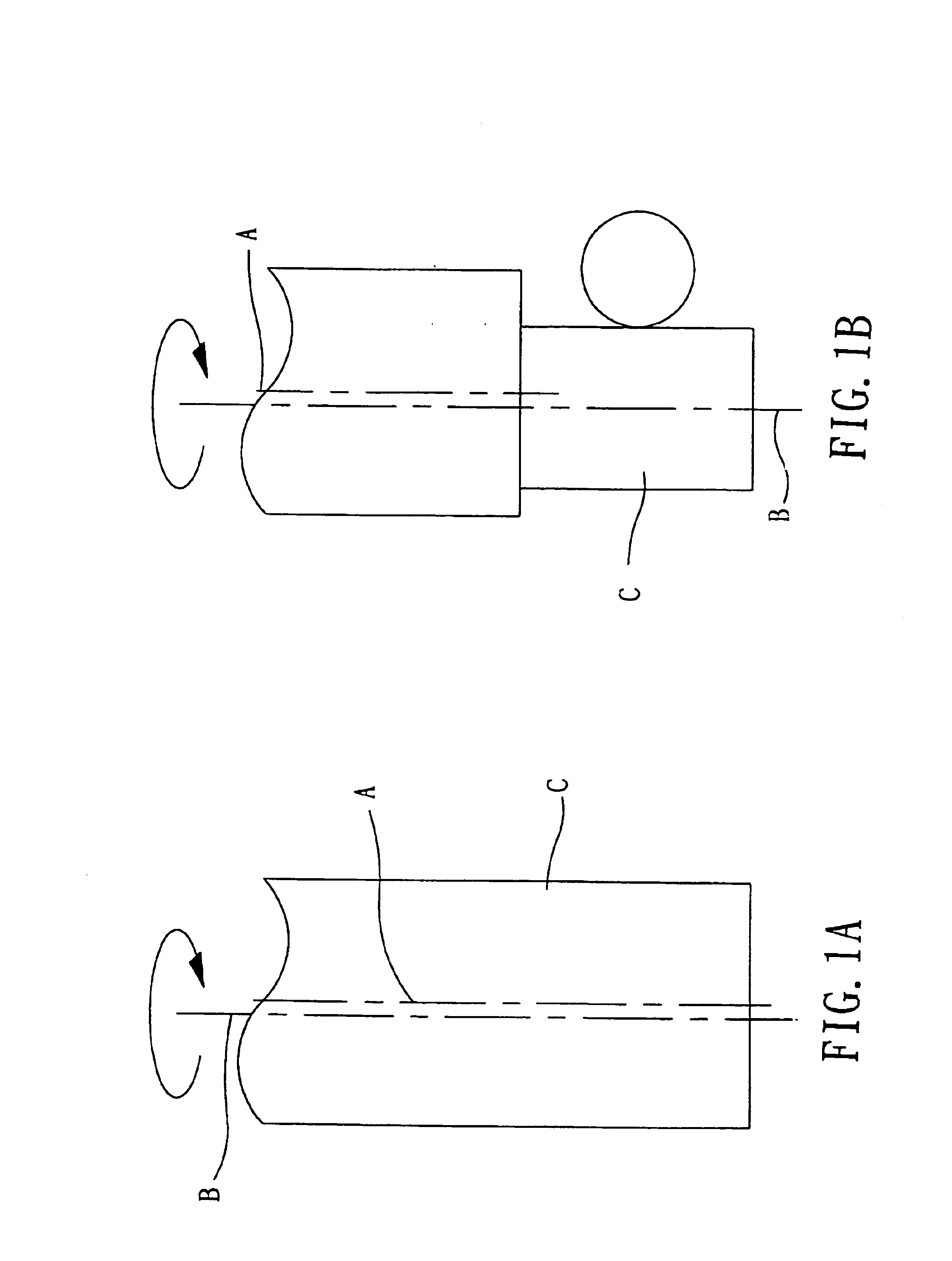
FIELD OF THE INVENTIONThe invention relates to a microelectrode machining device, and more particularly to a microelectrode machining device capable of providing wire of high stability by changing the structure of the wire guide therein, and enabling the electrical discharge machining (EDM) to be performed on a microelectrode of non-cylindrical form, in addition, the device also may have a better machining precision.BACKGROUND OF THE INVENTIONFollowing the fast progress and development of technology, many machining techniques with high precision are developed, such as the technique of electrical discharge machining (EDM) which the material is removed by the erosive action of electrical discharges (sparks) provided by a generator. The same phenomenon of EDM is applied at the micron level for micromachining. The process is called as micro-EDM. In general, in the conventional micro-EDM process, there is an unavoidable offset between the electrode center A and the machining center B. Th...

Claims


Application Information

Patent Timeline
Patent Type & Authority Patents(United States)
IPC IPC(8): B23H7/02B23H7/10B23H7/08
CPCB23H7/105B23H7/02
Inventor YANG, CHING-CHENGLIN, JUI-KUANMAI, CHAO-CHUANGSU, HSIN-CHUAN
Owner IND TECH RES INST
Learn More