
Machining center

a technology of machining center and machining tool, which is applied in the direction of manufacturing tools, program control, instruments, etc., can solve the problems of misalignment between the workpiece and the machining tool, and achieve the effect of increasing the machining precision of the machining center

Active Publication Date: 2021-05-11
DN SOLUTIONS CO LTD
View PDF9 Cites 0 Cited by
  • Summary
  • Abstract
  • Description
  • Claims
  • Application Information

AI Technical Summary

Benefits of technology

The system automatically detects and corrects installation errors, enhancing machining precision by aligning the workpiece and machining tool, thereby improving the accuracy and reliability of machining processes despite bed deformation.

Problems solved by technology

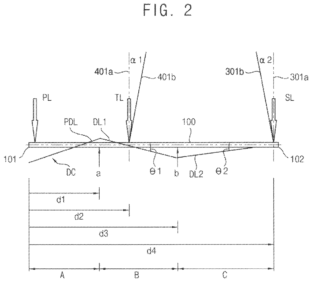
When the bed structure may be deformed in the longitudinal direction, an upper slope may occur on the upper surface of the bed structure in the longitudinal direction and as a result, the vertical axis of the table and the vertical beam of the spindle assembly may become slanted as much as the upper slope, which is referred as installation error of the table and the installation error of the spindle assembly, respectively.
The installation errors of the table and the spindle assembly necessarily cause the misalignment between the workpiece and the machining tool secured to the spindle assembly.
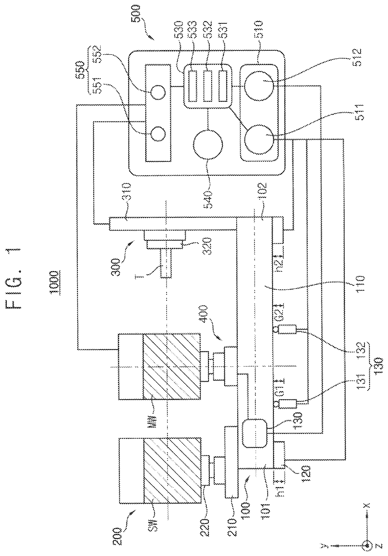
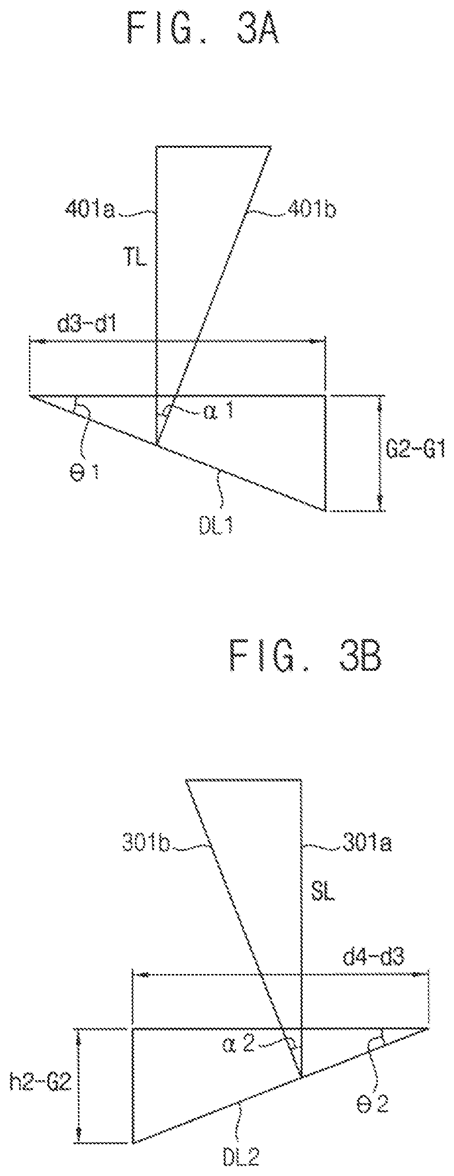
In example embodiments, the deflection curve may include a continuous polynomial curve in the longitudinal direction and the error generator may generate the first installation error as a slant angle of an instantaneous slope of the polynomial curve at the load point of the table loading and may generate the second installation error as a slant angle of an instantaneous slope of the polynomial curve at the second end portion of the bed structure.

Method used


Image

  • Machining center
  • Machining center
  • Machining center

Examples


Embodiment Construction

SCRIPTION OF EMBODIMENTS

[0065]Example embodiments will now be described more fully with reference to the accompanying drawings. Embodiments, however, may be embodied in many different forms and should not be construed as being limited to the embodiments set forth herein. Rather, these example embodiments are provided so that this disclosure will be thorough and complete, and will fully convey the scope to those skilled in the art. In the drawings, the thicknesses of layers and regions may be exaggerated for clarity.

[0066]It will be understood that when an element is referred to as being “on,”“connected to,”“electrically connected to,” or “coupled to” to another component, it may be directly on, connected to, electrically connected to, or coupled to the other component or intervening components may be present. In contrast, when a component is referred to as being “directly on,”“directly connected to,”“directly electrically connected to,” or “directly coupled to” another component, th...


PUM


Abstract

Disclosed is a machining center. The machining center includes a bed structure deflected along a deflection curve by a load distribution thereon, a palette structure secured to a first end portion of the bed structure, a spindle assembly to which a machining tool is secured and secured to a second portion of the bed structure, a table movably secured to the bed structure such that a table loading is applied to a load point of the bed structure and an automatic aligner automatically detecting first and second installation errors of the table and the spindle assembly and automatically correcting the first and the second installation errors such that the workpiece and the tool are aligned with each other. The misalignment between the workpiece and the tool is automatically detected and corrected in the machining center.

Description

CROSS-REFERENCE TO RELATED APPLICATION[0001]This application claims priority under 35 USC § 119 to Korean Patent Application No. 10-2016-0063581, filed on May 24, 2016, in the Korean Intellectual Property Office (KIPO), the content of which is incorporated by reference herein in its entirety.BACKGROUND1. Field[0002]The present inventive concepts relate to a machining center, and more particularly, to a horizontal machining center.2. Description of the Related Art[0003]Recently, a plurality of machining centers has been widely used for machining mechanical products in which most of machining processes for manufacturing the mechanical products can be automatically controlled under numerical control algorithms. For example, the boring process, the milling process, the reaming process and the rapping process can be executed on the same machining center just by automatically changing the machining tools.[0004]Particularly, a horizontal machining center is usually composed of a bed struct...

Claims


Application Information

Patent Timeline
Patent Type & Authority Patents(United States)
IPC IPC(8): B23Q3/154
CPCB23Q3/154B23C1/02B23C9/00B23Q11/00B23Q17/22G05B19/401B23Q15/22G05B19/404G05B2219/49189B23Q11/001B23Q17/2233B23C2270/00
Inventor SIM, JAE-DOO
Owner DN SOLUTIONS CO LTD
Learn More