Fuel injection valve and its apparatus, method for manufacturing internal combustion engine and fuel injection valve and its nozzle body, and method for manufacturing the same

a technology of fuel injection valve and nozzle body, which is applied in the direction of liquid fuel feeder, mechanical equipment, machines/engines, etc., can solve the problems of fuel spray shape instability, and achieve the effect of high accuracy and stabilized fuel spraying characteristics and excellent productivity

Inactive Publication Date: 2005-01-25
HITACHI LTD
View PDF10 Cites 9 Cited by
  • Summary
  • Abstract
  • Description
  • Claims
  • Application Information

AI Technical Summary

Benefits of technology

It is an object of the present invention to provide a fuel injection valve and its apparatus, and an internal combustion engine, a method for manufacturing the fuel injection valve and its nozzle body, and a method

Problems solved by technology

The hanging of forging of a binding wall forming a spray shape and a turning binding wall, or u

Method used


Image

  • Fuel injection valve and its apparatus, method for manufacturing internal combustion engine and fuel injection valve and its nozzle body, and method for manufacturing the same
  • Fuel injection valve and its apparatus, method for manufacturing internal combustion engine and fuel injection valve and its nozzle body, and method for manufacturing the same
  • Fuel injection valve and its apparatus, method for manufacturing internal combustion engine and fuel injection valve and its nozzle body, and method for manufacturing the same

Examples


Embodiment Construction

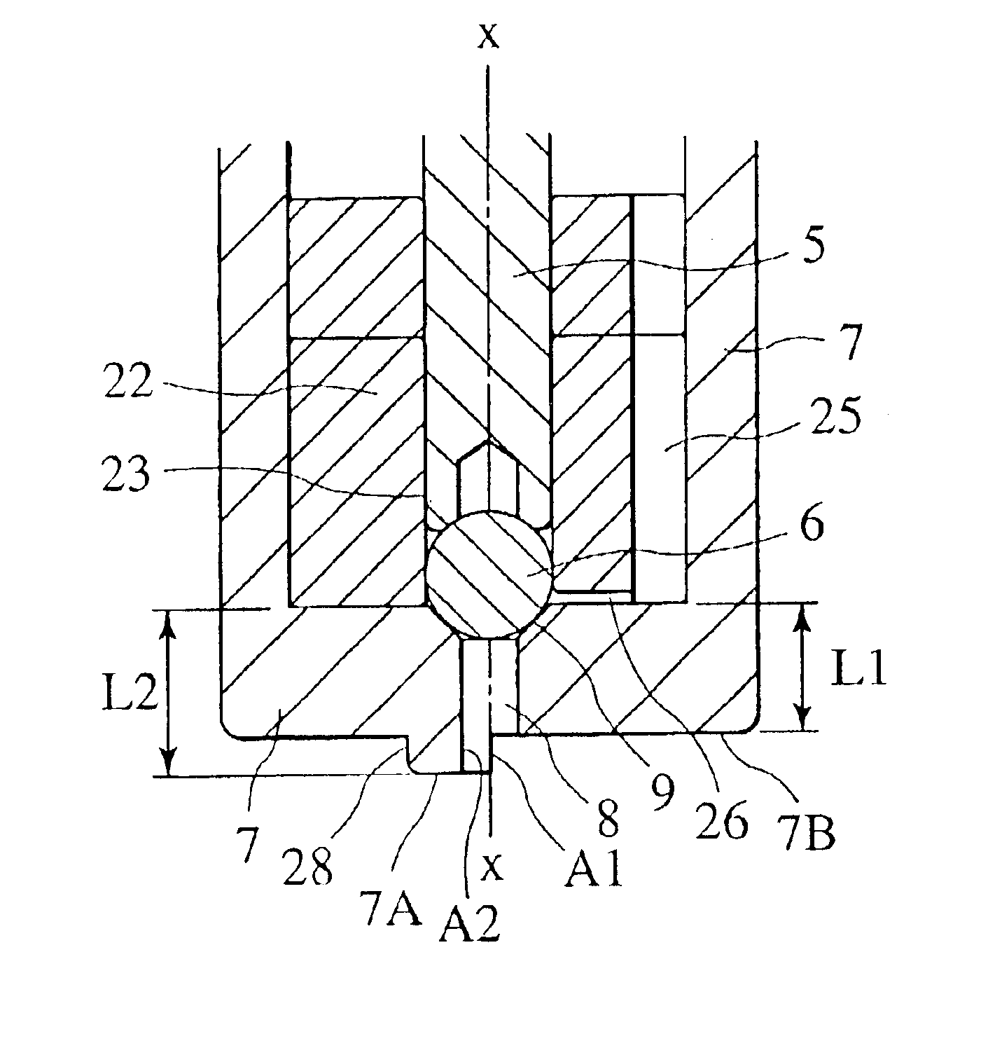
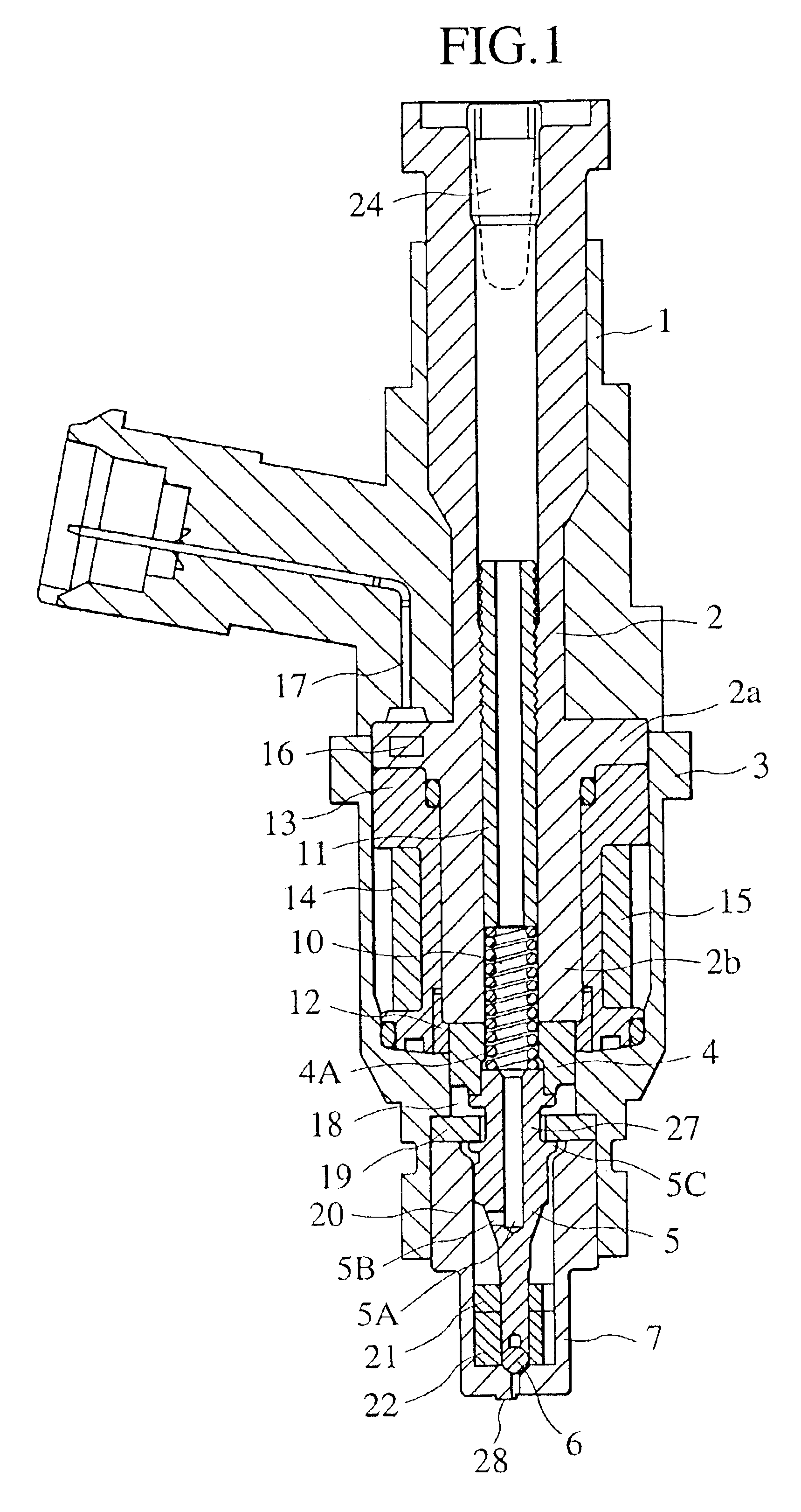
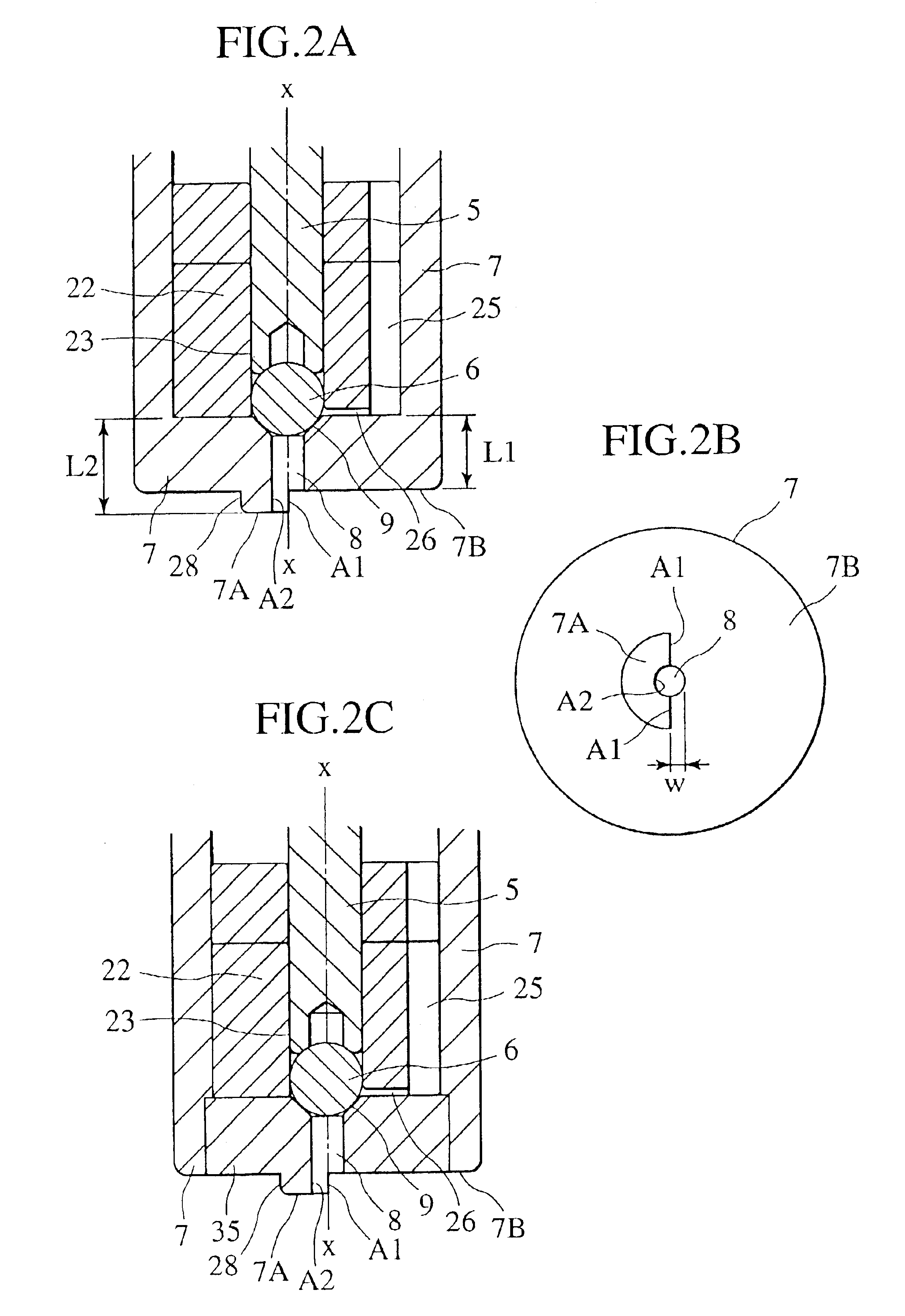
FIG. 1 is a sectional view of a fuel injection valve of the present invention. A fuel injection valve 1 injects fuel by opening and closing thereof caused by vertical movement of a ball 6 with respect to a seat portion of a nozzle body 7 described later by an ON-OFF signal of the duty arithmetically calculated by a control unit not shown.

In the following explanation, a surface parallel to a valve fuel injection valve axis, including a fuel injection valve axis (valve fuel injection valve shaft center), is called a longitudinal section, and a plane perpendicular to a valve fuel injection valve axis is called a cross section.

A magnetic circuit comprises a yoke 3, a core 2 comprising a plug portion 2a for closing an upper opened end of the yoke 3 and a columnar portion 2b extending to the center of the yoke 3, and an anchor 4 facing to the core 2 through a gap. The columnar portion 2 is provided in its center with a hole 4A for holding a coil spring 10 which acts to press, toward a sea...


PUM


Abstract

It is an object of the present invention is to provide a fuel injection valve and its apparatus, and an internal combustion engine, a method for manufacturing the fuel injection valve and its nozzle body, and a method for manufacturing the same capable of securing highly accurate and stabilized fuel spraying characteristics. The fuel injection valve comprises a nozzle body, an injection hole provided in the nozzle body, a valve body for opening and closing a fuel passage from the injection hole relative to the nozzle body, and a drive means for driving the valve body, wherein formed is a protrusion having an opening in communication with the downstream side of the injection hole of the nozzle body and which part of the side and an extreme end are opened. The invention resides in a nozzle body and manufacturing it by plastic processing, and an internal combustion engine using the same.

Description

BACKGROUND OF THE INVENTIONThe present invention relates to a new fuel injection valve and its apparatus, and an internal combustion engine, a method for manufacturing the fuel injection valve and its nozzle body, and a method for manufacturing the same, and particularly relates to a fuel injection valve capable of controlling a spry shape of fuel to be injected (the nozzle body is hereinafter referred to as an L step nozzle), its apparatus, an internal combustion engine, a method for manufacturing the same, its nozzle body and a method for manufacturing the same.The art in which a nozzle shape of a fuel injection valve for injection fuel directly into the cylinder of the internal combustion engine is adjusted to the size and shape of an in-cylinder injection engine and using conditions is known in Japanese Patent Laid-open No. 329036 / 2002. In this publication, there is described that the shape of a nozzle is prepared by a processing method such as press processing (plastic processi...

Claims


Application Information

Patent Timeline
IPC IPC(8): F02M61/18F02M61/00F02M61/16F02M51/06F02M63/00F02M69/04F02M61/04
CPCF02M51/0671F02M61/162F02M61/168F02M61/188F02M61/18F02M2200/505F02M69/045
Inventor KOBAYASHI, MASAYUKIHARADA, KOJIISHIKAWA, TORU
Owner HITACHI LTD
Why Eureka
Try Eureka