
Rankine cycle device of internal combustion engine

a technology of internal combustion engine and cycle device, which is applied in the direction of steam engine plants, machines/engines, mechanical equipment, etc., can solve the problems of large difference between the pressures, combustion engine overheating, and rankine cycle system cannot exhibit a sufficient performan

Inactive Publication Date: 2005-01-25
HONDA MOTOR CO LTD
View PDF7 Cites 24 Cited by
  • Summary
  • Abstract
  • Description
  • Claims
  • Application Information

AI Technical Summary

Benefits of technology

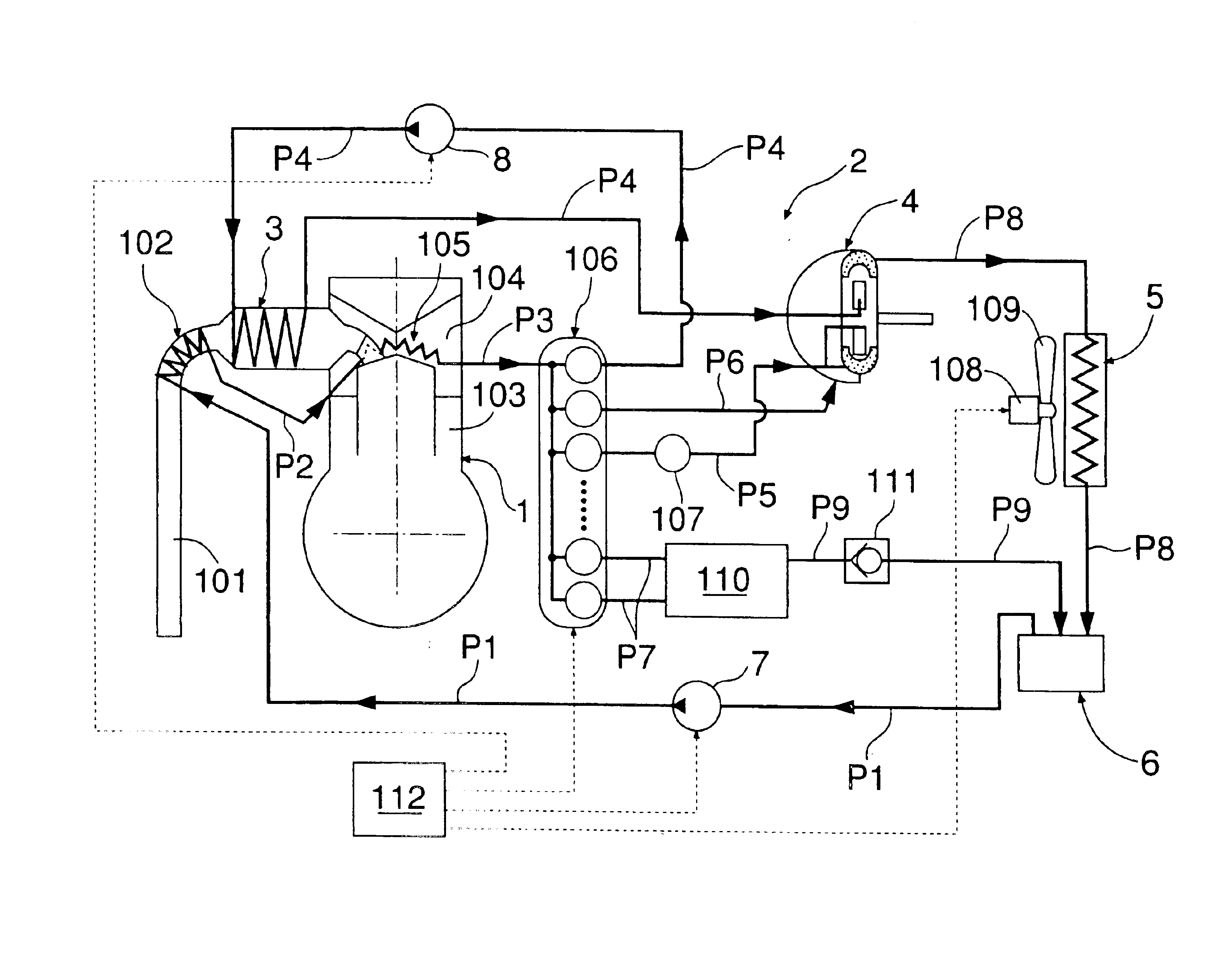
With the above arrangement, the liquid-phase working medium in the tank is supplied to the cooling means for the internal combustion engine by the lower pressure pump to cool heated portions of the internal combustion engine, and thereafter, a portion of the liquid-phase working medium exiting from the cooling means is supplied from the dispensing valve to the higher-pressure pump and supplied in a pressurized state to the evaporator in the Rankine cycle system, while another portion of the liquid-phase working medium exiting from the cooling means is supplied from the dispensing valve to the auxiliary, and the liquid-phase working medium exiting from the expander in the Rankine cycle system and liquefied through the condenser and the liquid-phase working medium dissipating its heat in the auxiliary are returned to the tank. Therefore, it is possible to supply the liquid-phase working mediums having flow rates and pressures suitable respectively for the Rankine cycle system and the cooling means, while uniting a liquid-phase working medium-circulating line in the Rankine cycle system and a liquid-phase working medium-circulating line in the cooling means for the internal combustion engine. Thus, it is possible to cool the heated portions of the internal combustion engine sufficiently, while maintaining the performance of the Rankine cycle system, thereby aiming at the disused of a radiator.
With the above arrangement, the liquid-phase working medium supplied from the lower-pressure pump to the cooling means is preheated in the exchanger mounted in the exhaust pipe and hence, it is possible not only to utilize a waste heat of an exhaust gas further effectively, but also to prevent the occurrence of the overcooling by the liquid-phase working medium passed through the cooling means when the internal combustion engine is at a lower temperature, thereby promoting the warming of the internal combustion engine.
With the above arrangement, a portion of the heated liquid-phase working medium dispensed from the dispensing valve is used as a lubricating medium for the expander and hence, it is possible to prevent the dropping of the temperature of the expander due to the lubricating medium having a lower temperature to suppress the reduction of the expanding work, thereby enhancing the efficiency of recovery of the waste heat from the internal combustion engine.
With the above arrangement, the portion of the liquid-phase working medium supplied as the lubricating medium is supplied in the form of the gas-phase working medium to the expansion stroke of the expander and hence, the heat energy own by the liquid-phase working medium serving as the lubricating medium can be utilized effectively to increase the output from the expander.
With the above arrangement, the portion of the heated liquid-phase working medium dispensed from the dispensing valve is converted into the gas-phase working medium by the reducing valve, which is supplied to the expansion stroke of the expander, and hence, a heat energy received from the heated portions of the internal combustion engine by the liquid-phase working medium can be utilized effectively to increase the output from the expander.
With the above arrangement, the water, having a wide range of temperature in which it can be used without variation in composition such as carbonization and the like, is used as the liquid-phase working medium. Therefore, the gas-phase working medium in a higher-temperature state supplied to the expander and the liquid-phase working medium in a lower-temperature state discharged from the cooling medium for the internal combustion engine can be merged into each other without hindrance and moreover, when water is used as the lubricating medium, the working medium and the lubricating medium can be mixed with each other without hindrance.

Problems solved by technology

The pressure of the water supplied to the evaporator in the Rankine cycle system is about 100 times the pressure of the cooling water supplied to the water jacket of the internal combustion engine, resulting in a large difference existing between both of the pressures.
Therefore, it is virtually difficult, because of a large difference in flow rate and pressure between the water-circulating paths, to connect a water-circulating path in the Rankine cycle system and a water-circulating path for the internal combustion engine in line to each other to aim at the disuse of a radiator, and there is a possibility that the internal combustion engine might be overheated and that the Rankine cycle system could not exhibit a sufficient performance.

Method used


Image

  • Rankine cycle device of internal combustion engine
  • Rankine cycle device of internal combustion engine
  • Rankine cycle device of internal combustion engine

Examples


Embodiment Construction

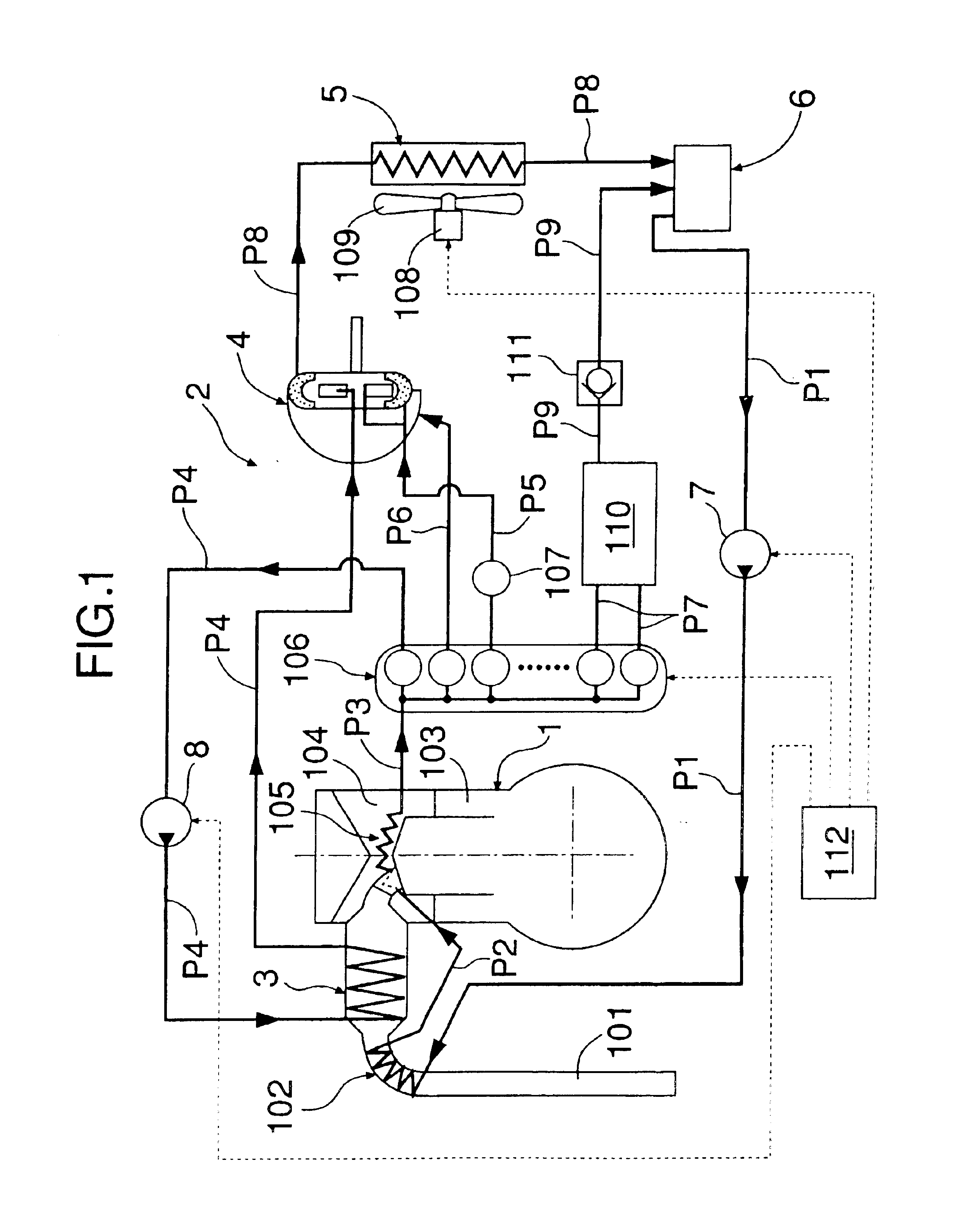
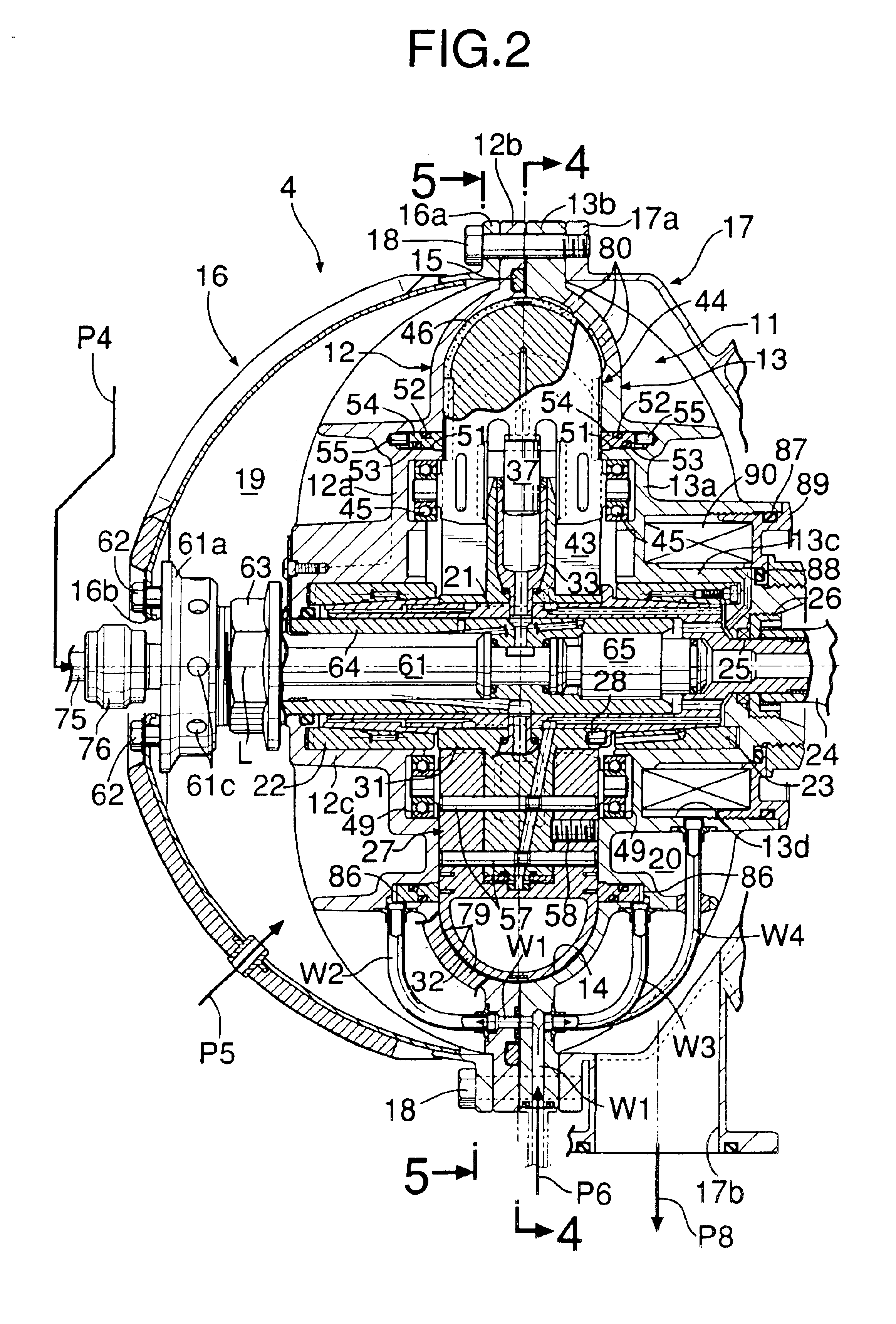
As shown in FIG. 1, a Rankine cycle system 2 for recovering a heat energy of an exhaust gas from an internal combustion engine 1 to output a mechanical energy includes an evaporator 3 for generating a high-temperature and high-pressure vapor by heating water using the exhaust gas from the internal combustion engine 1 as a heat source, an expander 4 for outputing a shaft torque by the expansion of the high-temperature and high-pressure vapor, a condenser 5 for cooling a dropped-temperature and dropped-pressure vapor discharged from the expander 4 to liquefy it, a tank 6 for storage of the water discharged from the condenser 5, and a lower-pressure pump 7 and a higher-pressure pump 8 for supplying the water in the tank 6 again to the evaporator 3.

The water in the tank 6 is pressurized to 2 to 3 MPa by the lower-pressure pump 7 disposed on a passage P1 and passed through a heat exchanger 102 mounted in an exhaust pipe 101 for the internal combustion engine 1, where it is preheated. The...


PUM


Abstract

In a Rankine cycle system for an internal combustion engine, including an evaporator (3) for generating a vapor, an expander (4) for converting a heat energy of the vapor into a mechanical energy, a condenser (5) for cooling the vapor discharged from the expander (4) to restore it into water, a tank (6) for storage of the water from the condenser (5), and supply pumps (7, 8) for supplying the water in said tank (6) to the evaporator (3) in a pressurizing manner, the water in the tank (6) is supplied via a water jacket (105) of the internal combustion engine (1) to a dispensing valve (106) by the lower-pressure pump (7). A portion of the water dispensed by the dispensing valve (106) is further pressurized and supplied to the evaporator (3) by the higher-pressure pump (8), and another portion of the water dispensed by the dispensing valve (106) is discharged to the tank (6) after dissipating its heat in an auxiliary (110) such as a heater for heating a vehicle compartment and the like. Thus, it is possible to sufficiently cool heated portions of the internal combustion engine (1) by the water which is a liquid-phase working medium, while maintaining the performance of the Rankine cycle system, thereby aiming at the disuse of a radiator.

Description

FIELD OF THE INVENTIONThe present invention relates to a Rankine cycle system utilizing a waste heat from an internal combustion engine, and particularly, to a Rankine cycle system designed so that heated portions of an internal combustion engine can be cooled by a working medium.BACKGROUND ARTA Rankine cycle system is described in Japanese Utility Model Application Laid-open No.59-174308, which includes an evaporator for heating a liquid-phase working medium by an exhaust gas from an internal combustion engine to generate a gas-phase working medium, an expander driven by the gas-phase working medium generated in the evaporator, a condenser for cooling the gas-phase working medium passed through the expander to restore it into the liquid-phase working medium, and a supply pump for supplying the liquid-phase working medium from the condenser in a pressurizing manner to the evaporator.In the above-described conventional Rankine cycle system, the water as the liquid-phase working mediu...

Claims


Application Information

Patent Timeline
IPC IPC(8): F01K23/06F01K23/10F01N5/00F01N5/02F02G5/00F02G5/02F02G5/04
CPCF01K23/065F01K23/106F01N5/02F02G5/04F02G5/02Y02T10/166Y02T10/16Y02T10/12F01K23/10
Inventor NIIKURA, HIROYUKITANIGUCHI, HIROYOSHIUDA, MAKOTOKATAHIRA, KIYOSHI
Owner HONDA MOTOR CO LTD
Learn More