
Method of driving a shift register, a shift register, a liquid crystal display device having the shift register

a shift register and shift register technology, which is applied in the direction of static storage, digital storage, instruments, etc., can solve the problems of low price, low power consumption, and complex manufacturing processes, and achieve the effect of reducing the size of the pull-down transistor that contributes to the capacitive load of the shift register, reducing the operation speed of the inverter, and not deteriorating the image display quality

Inactive Publication Date: 2005-01-18
SAMSUNG DISPLAY CO LTD
View PDF1 Cites 298 Cited by
  • Summary
  • Abstract
  • Description
  • Claims
  • Application Information

AI Technical Summary

Benefits of technology

This solution minimizes signal delay, maintains image display quality, and enhances manufacturing yield by reducing transistor size and power consumption, while being independent of threshold voltage variations and peripheral temperature changes.

Problems solved by technology

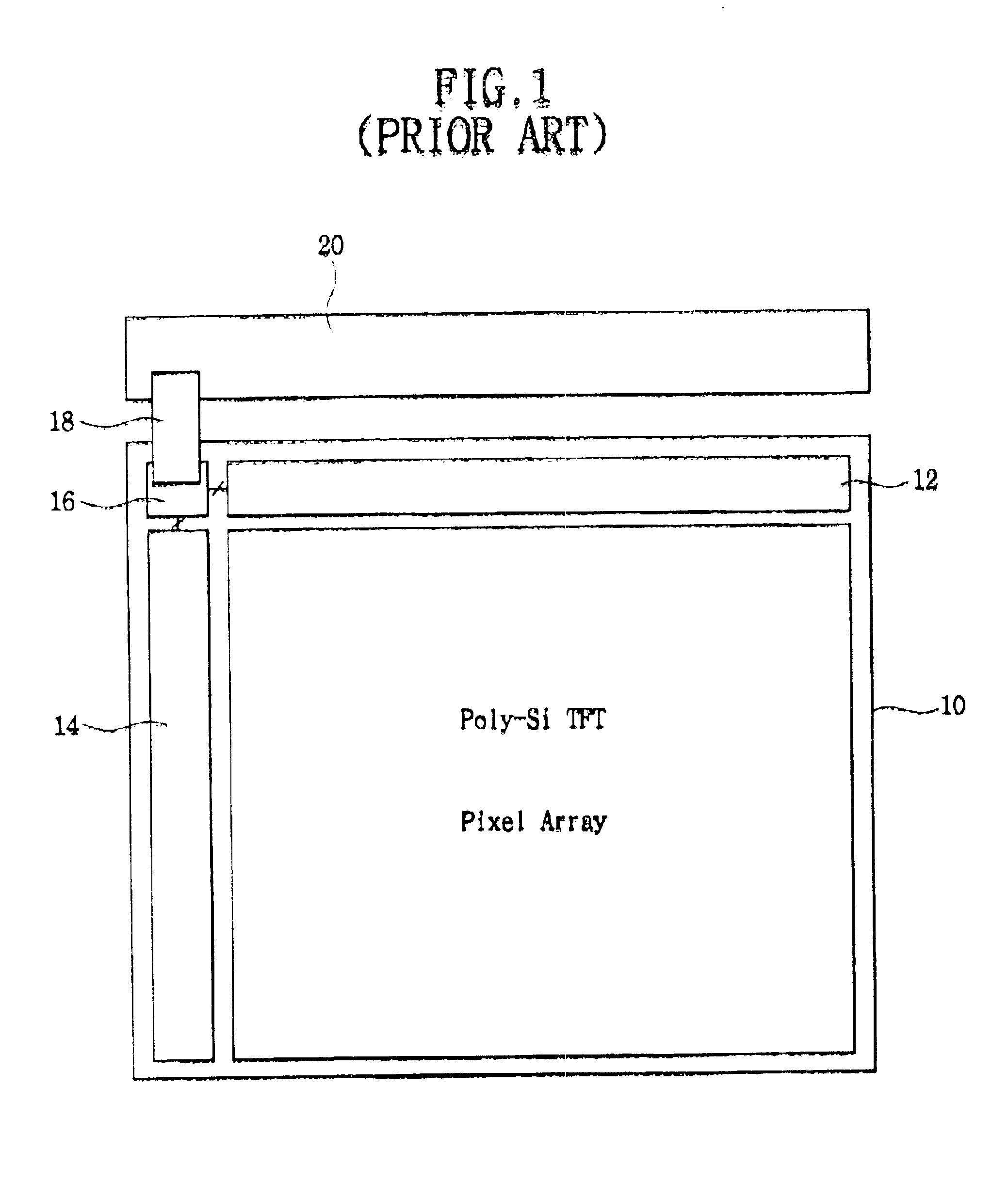
The poly-silicon TFT LCD (or poly-Si TFT LCD) device has lower power consumption and a low price, but is manufactured through complex processes compared with the a-Si TFT LCD device.
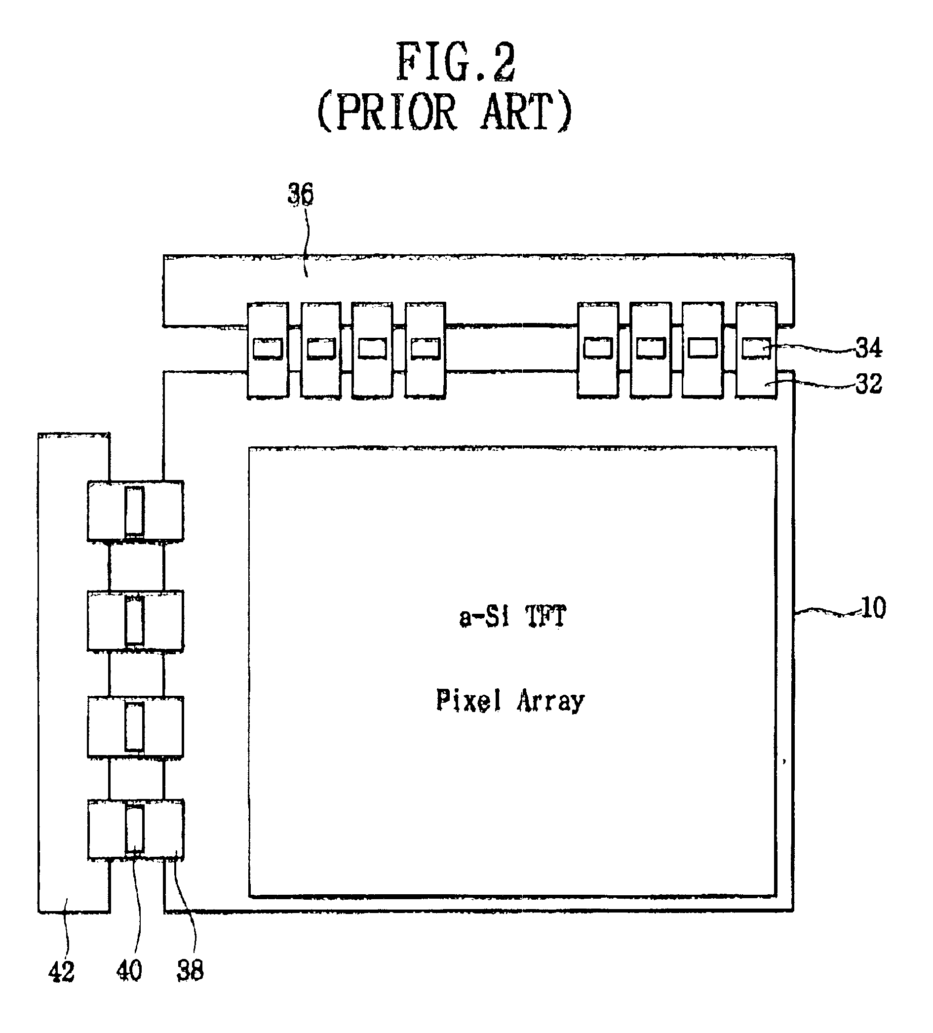
The a-Si TFT LCD device has an advantage in aspect of yield (or productivity), but has disadvantage in aspect of manufacturing cost and thickness.
However, deterioration of display quality may occur when the conventional gate driver circuit is used in the a-Si TFT LCD device having a large display screen.

Method used


Image

  • Method of driving a shift register, a shift register, a liquid crystal display device having the shift register
  • Method of driving a shift register, a shift register, a liquid crystal display device having the shift register
  • Method of driving a shift register, a shift register, a liquid crystal display device having the shift register

Examples


Embodiment Construction

Hereinafter the preferred embodiment of the present invention will be described in detail with reference to the accompanying drawings.

FIG. 3 is an exploded perspective view showing an a-Si thin film transistor LCD according to one exemplary embodiment of the present invention.

Referring to FIG. 3, the liquid crystal display device 100 includes a liquid crystal display panel assembly 110, a backlight assembly 120, a chassis 130 and a cover case 140.

The liquid crystal display panel assembly 110 includes a liquid crystal display panel 112, a flexible printed circuit board 116 and an integrated control chip 118. The liquid crystal display panel 112 includes a TFT substrate 112a and a color filter substrate 112b.

A display cell array, a data driver circuit, a gate driver circuit and external connection terminals are formed on the TFT substrate 112a. Color filters and transparent common electrodes are formed on the color filter substrate 112b. The color filter substrate 112b faces the TFT ...


PUM

PropertyMeasurementUnit
voltageaaaaaaaaaa
voltageaaaaaaaaaa
widthaaaaaaaaaa

Abstract

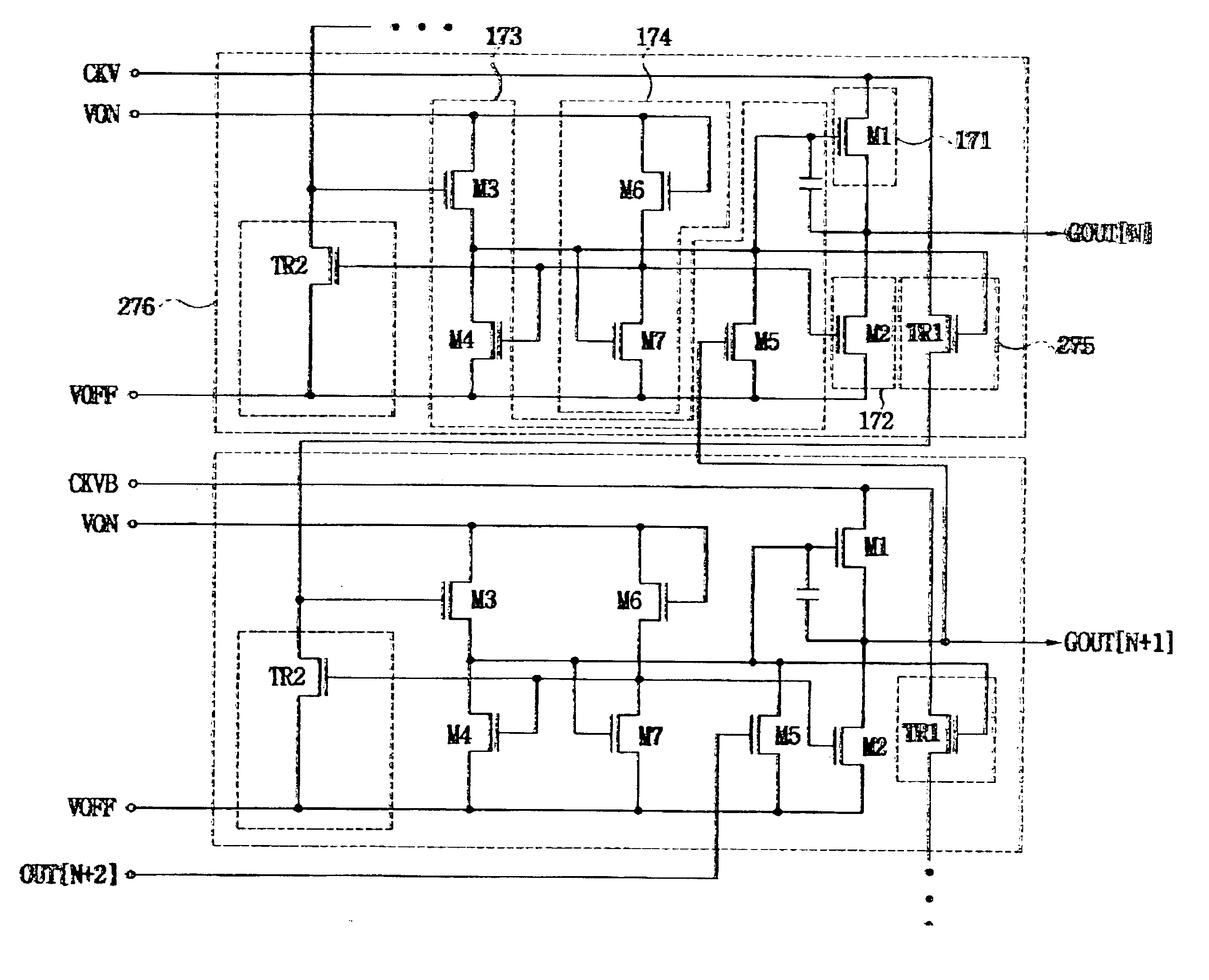
In a shift register and LCD device having the shift register that may be employed in the liquid crystal display device having a large screen size and a large resolution, the shift register includes stages cascade-connected with each other and each of the stages have a carry buffer for generating a carry signal. The pull-down transistor of each of the stages of the shift register is divided into a first pull-down transistor and a second pull-down transistor. A power voltage Vona larger than the power voltage Von applied to a clock generator is applied to the shift register. A signal delay due to the RC delay of the gate lines may be minimized, the shift register is independent of the variation of the threshold voltage of the TFTs, and image display quality may not be deteriorated.

Description

CROSS-REFERENCE TO RELATED APPLICATIONSThis application relies for priority upon Korean Patent Application No. 2002-33455 filed on Jun. 15, 2002, Korean Patent Application No. 2002-37946 filed on Jul. 2, 2002, Korean Patent Application No. 2002-39129 filed on Jul. 6, 2002 and Korean Patent Application No. 2003-6683 filed on Feb. 4, 2003, the contents of which are herein incorporated by reference in their entirety.BACKGROUND OF THE INVENTION1. Field of the InventionThe present invention relates to a method of driving a shift register, a shift register, and a liquid crystal display (LCD) device having the shift register. More particularly, the present invention relates to a method of driving a shift register that may be used in an a-Si thin film transistor liquid crystal display device (a-Si TFT LCD) having a large display screen, a shift register, and a liquid crystal display (LCD) device having the shift register.2. Description of the Related ArtThe TFT LCD device is classified into...

Claims


Application Information

Patent Timeline
Patent Type & Authority Patents(United States)
IPC IPC(8): G11C19/00G09G3/20G02F1/133G09G3/36
CPCG09G3/3685G11C19/28G09G2310/0286
Inventor MOON, SEUNG-HWANLEE, BACK-WON
Owner SAMSUNG DISPLAY CO LTD
Learn More