Multi-mode GPS receiver
a multi-mode, receiver technology, applied in the field of data transmission, can solve the problem that the host device does not provide the rs-232 interface, and achieve the effect of minimal or no impa
- Summary
- Abstract
- Description
- Claims
- Application Information
AI Technical Summary
Benefits of technology
Problems solved by technology
Method used
Image
Examples
first embodiment
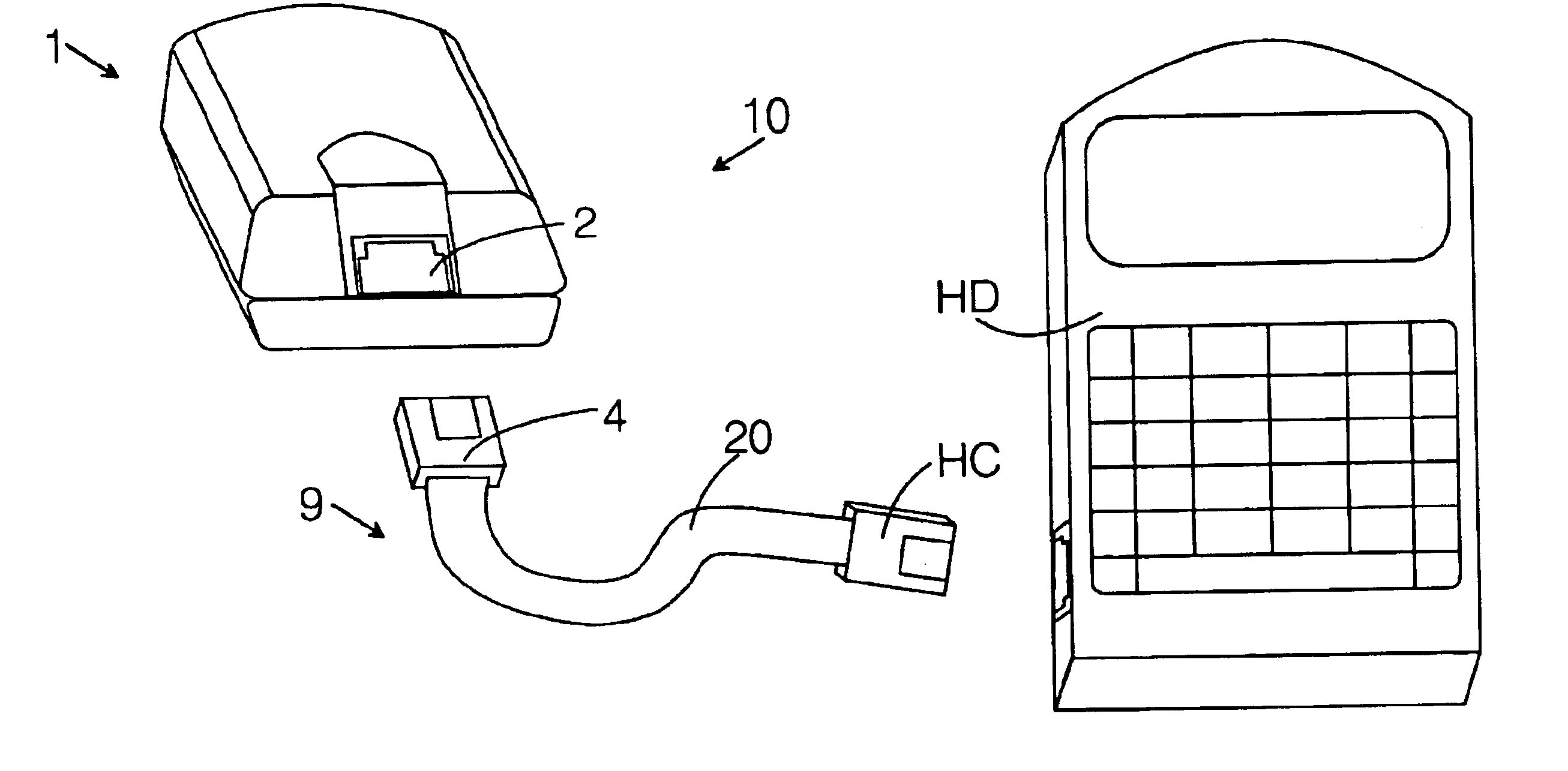
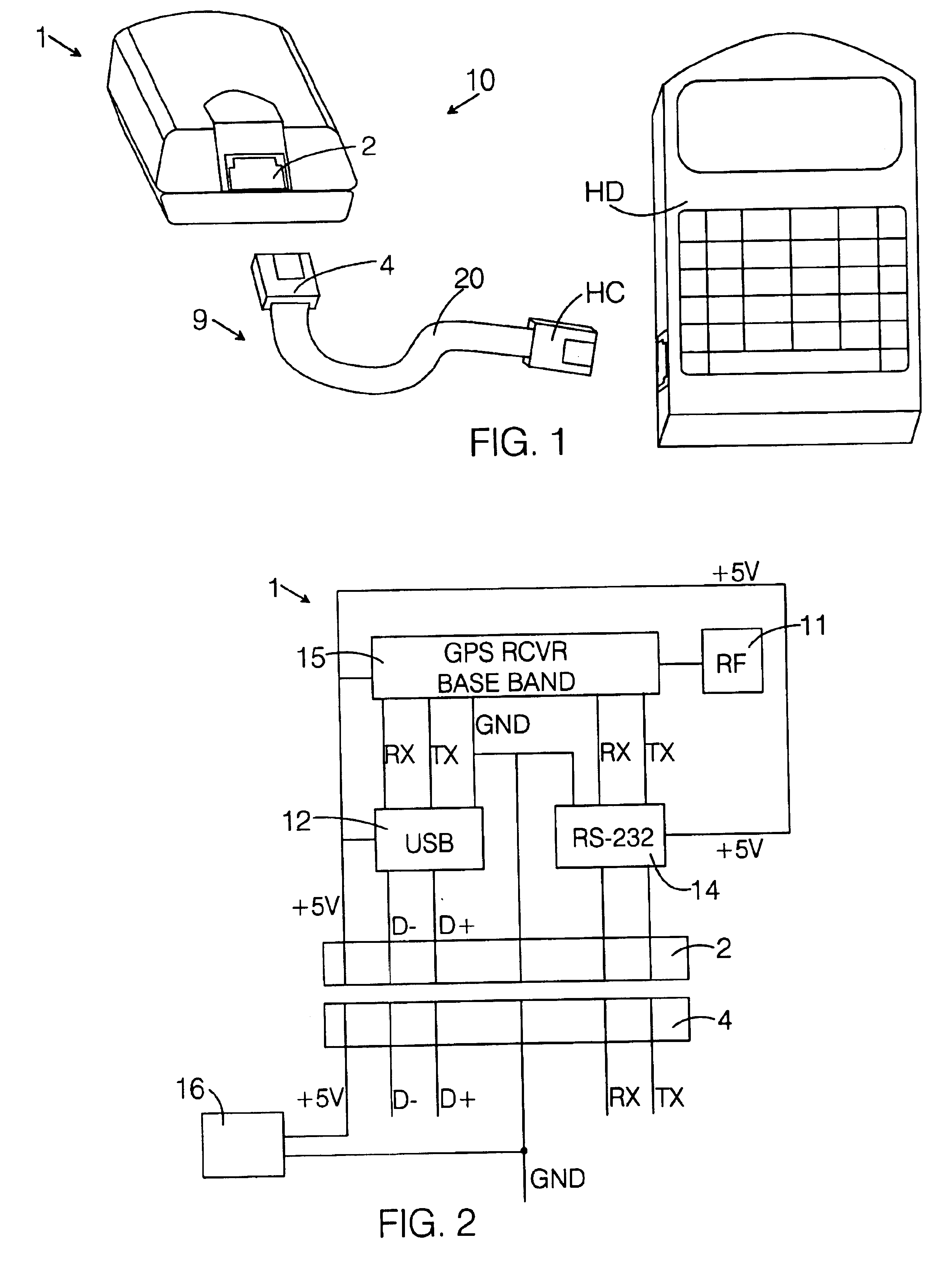
FIGS. 1 and 2 show a GPS data transceiver system 10 according to the invention. The GPS data transceiver system 10 includes a multi-mode GPS receiver 1 and a basic cable assembly 9 that connects the GPS receiver 1 with a host device HD. The host device HD may be any one of a number of computer host devices, such as a portable personal computer, a personal digital assistant, a data logger, etc. The GPS receiver 1 has a multi-mode female connector 2, no display capability, no power source, and no separate connector for receiving power. The basic cable assembly 9 includes a conventional data transmission cable 20 with a multi-mode male connector 4 at one end and a host connector HC at the other end. The multi-mode male connector 4 is connectable to the multi-mode female connector 2 and the host connector HC to the host device HD. In the embodiment shown, the multi-mode male connector 4 is a standard RJ11 male connector and the multi-mode female connector 2 is a standard RJ11 female con...
second embodiment
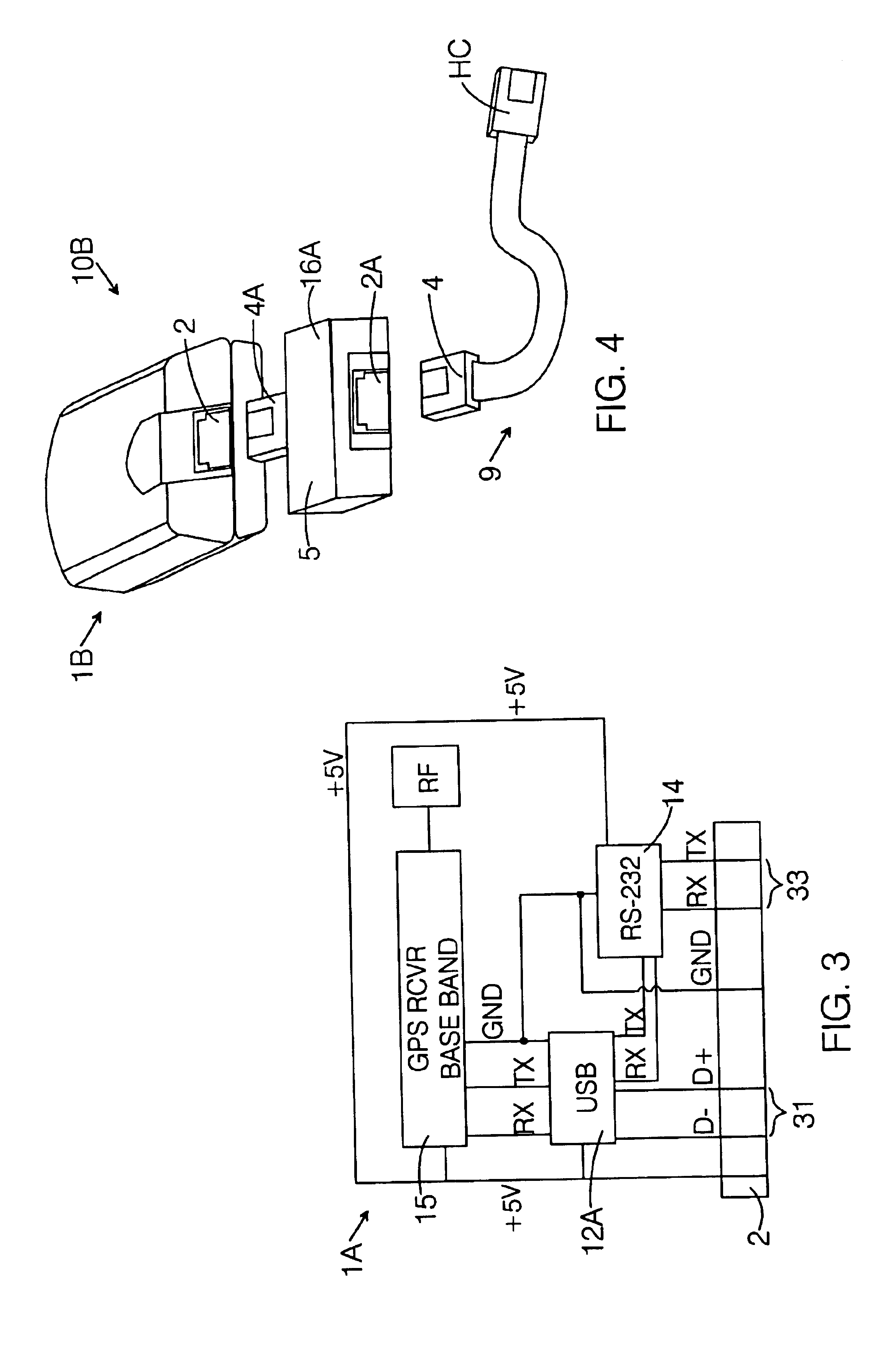
FIG. 3 is a schematic of a GPS data transceiver system 10A that includes a modified multi-mode GPS receiver 1A. As can be seen, the RS-232 circuitry ties into a USB microcontroller 12A. Suitable components for this circuitry are obtainable from Microchip Technology (PIC 16C745) and Cypress Semiconductor (CY7C63001A). When the GPS receiver 1A transceives data, the microcontroller 12A shuts down the RS-232 circuit if it detects signal on the USB port 31 and not at the RS-232 port 33, and vice versa, thereby reducing power consumption.
Both embodiments of the GPS data transceiver system 10, 10A shown in FIGS. 2 and 3, respectively, permit data to be transceived simultaneously under USB and RS-232 protocols. With the circuit configuration shown in FIG. 2, the GPS base band has two serial outputs and so, is capable of running data under the RS-232 protocol from one port and under the USB protocol from the other port. With the circuit configuration shown in FIG. 3, the GPS base band has on...
fourth embodiment
FIGS. 8 and 9 are schematic illustrations of a GPS data transceiver system 10D according to the invention. The GPS data transceiver system 10D includes a modified GPS receiver 1D that incorporates a conventional I2C flash memory chip 74, either in a modified battery pack 72 or in a separate pass-through data-logging module. FIG. 8 shows the modified GPS receiver 1D with a modified multi-mode connector 2B, and a cable assembly 11 that includes the RS-232 data transmission cable 21 and the host connector 8, as well as an I2C interface cable 23 that connects to a data logger 70. FIG. 9 illustrates schematically the electrical connections in the modified multi-mode connector 2B, which now comprises 8 pins. The additional two pins provide the means for implementing a simple, inexpensive, yet flexible method of data logging. The I2C bus includes two lines, a clock line (SCL) and a data line (SDA), and provides an interface between a master and a slave. In the method according to the inven...
PUM
 Abstract
Description
Claims
Application Information
 - R&D
- Intellectual Property
- Life Sciences
- Materials
- Tech Scout
- Unparalleled Data Quality
- Higher Quality Content
- 60% Fewer Hallucinations
Browse by: Latest US Patents, China's latest patents, Technical Efficacy Thesaurus, Application Domain, Technology Topic, Popular Technical Reports.
© 2025 PatSnap. All rights reserved.Legal|Privacy policy|Modern Slavery Act Transparency Statement|Sitemap|About US| Contact US: help@patsnap.com


