
Method and system for interacting with a vehicle over a mobile radiotelephone network

a mobile radiotelephone network and vehicle technology, applied in the direction of instruments, anti-theft devices, high-level techniques, etc., can solve the problems of inefficiency of the technique, the inability to communicate over a wireless network, and the inability to assign each min at the same time, so as to achieve the effect of minimal or no impact on the voice-carrying capacity of the cmr system

Active Publication Date: 2008-09-04
SIERRA WIRELESS AMERICA
View PDF101 Cites 20 Cited by
  • Summary
  • Abstract
  • Description
  • Claims
  • Application Information

AI Technical Summary

Benefits of technology

The system enables efficient power management, reduces communication latency, and provides timely and relevant data to users, enhancing vehicle monitoring and control capabilities while preserving battery life.

Problems solved by technology

This technique is often inefficient and limited in terms of its speed of message delivery.
CMR systems typically do not have an unlimited number of MINs, and assignment of each MIN incurs an associated cost.
Thus, one disadvantage of this technique is its consumption of MINs.
One problem with this scheme is that the RECC typically does not become immediately available for sending a reply following transmission of the instruction on the FOCC.
One shortcoming of this conventional scheme is that the communication latency or time delay can pose problems for telemetry applications.
For example, the 130-second delay can be unacceptable in certain time-critical circumstances.
If a vehicle owner needs to find his or her vehicle, the owner may lack the patience or the time to wait 130 seconds or some other significant period of time to receive the vehicle's location over a conventional overhead control channel.
Power consumption or battery life often poses another problem for many conventional telemetry systems mounted in vehicles for mobile operations.
That is, telemetry devices based on conventional technology may not offer a sufficient level of energy efficiency.
If all of the subsystems associated with the telemetry system are powered up and operational and the vehicle's alternator is not recharging the vehicle's battery, the total power consumption may pose an unacceptable battery drain.
On the other hand, if all of the vehicle's telemetry capabilities are turned off or disconnected from the battery, all telemetry functionality may be lost.
Conventional telemetry systems often fail to operate in a manner that adequately preserves battery life while providing an acceptable level of functionality or readiness.
However, to maintain the desired level of readiness, a conventional telemetry system may drain the vehicle's battery in an unacceptably short period of time.
Another problem with some conventional telemetry systems that monitor vehicles is that they may fail to provide a sufficient level of functional capability.
However, the telemetry system may fail to consider the circumstances surrounding the event or other events that preceded or followed that event.
In other words, conventional technology for vehicle telemetry may not provide an adequate level of processing or analysis of sensor data.
Without adequate processing of sensor data, a user of the telemetry system may be overwhelmed with extraneous data or false alarms.
Thus, telemetry systems based on conventional technology may not adequately highlight operating conditions or events of potential concern to the vehicle's owner.

Method used


Image

  • Method and system for interacting with a vehicle over a mobile radiotelephone network
  • Method and system for interacting with a vehicle over a mobile radiotelephone network
  • Method and system for interacting with a vehicle over a mobile radiotelephone network

Examples


Embodiment Construction

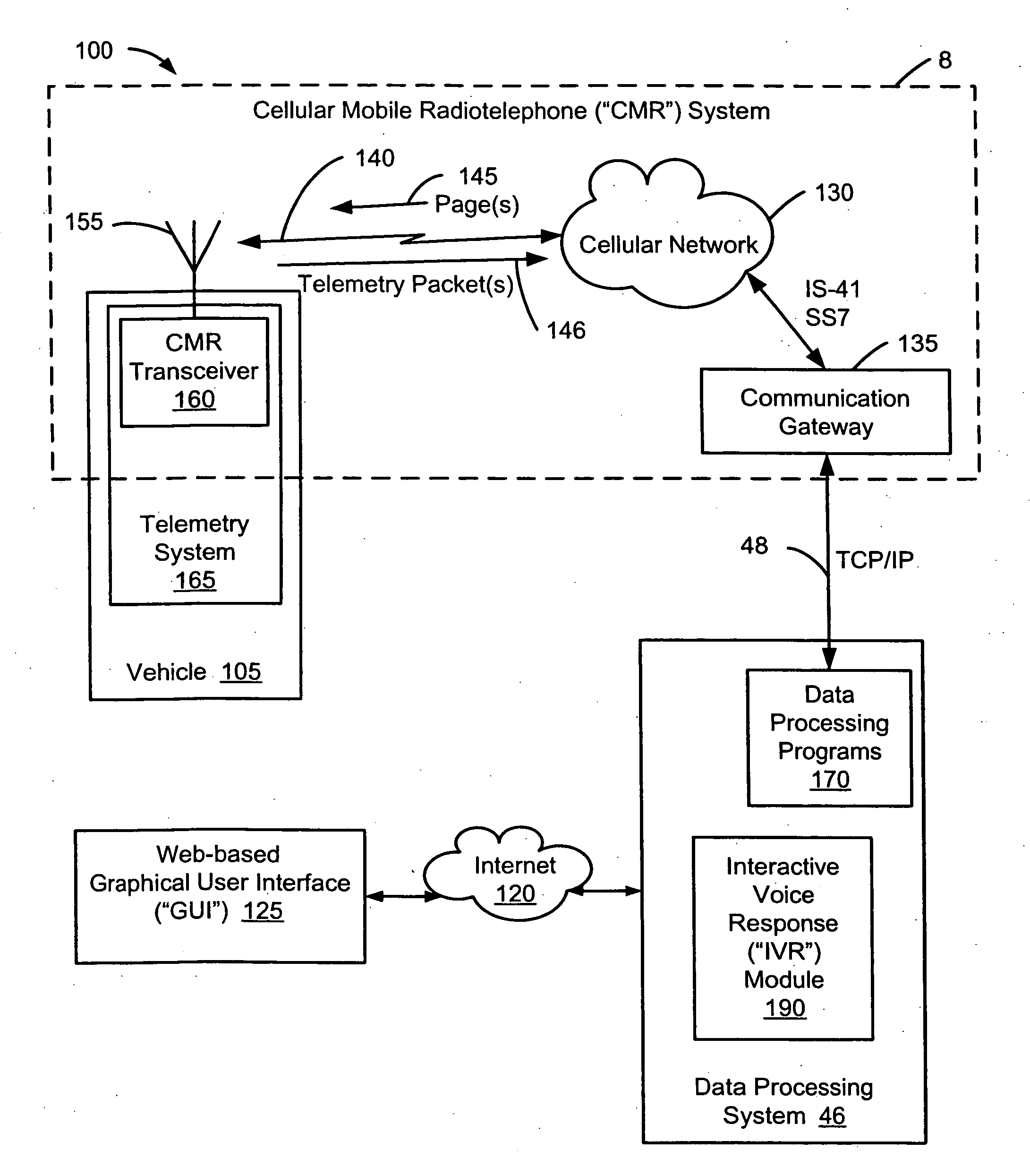
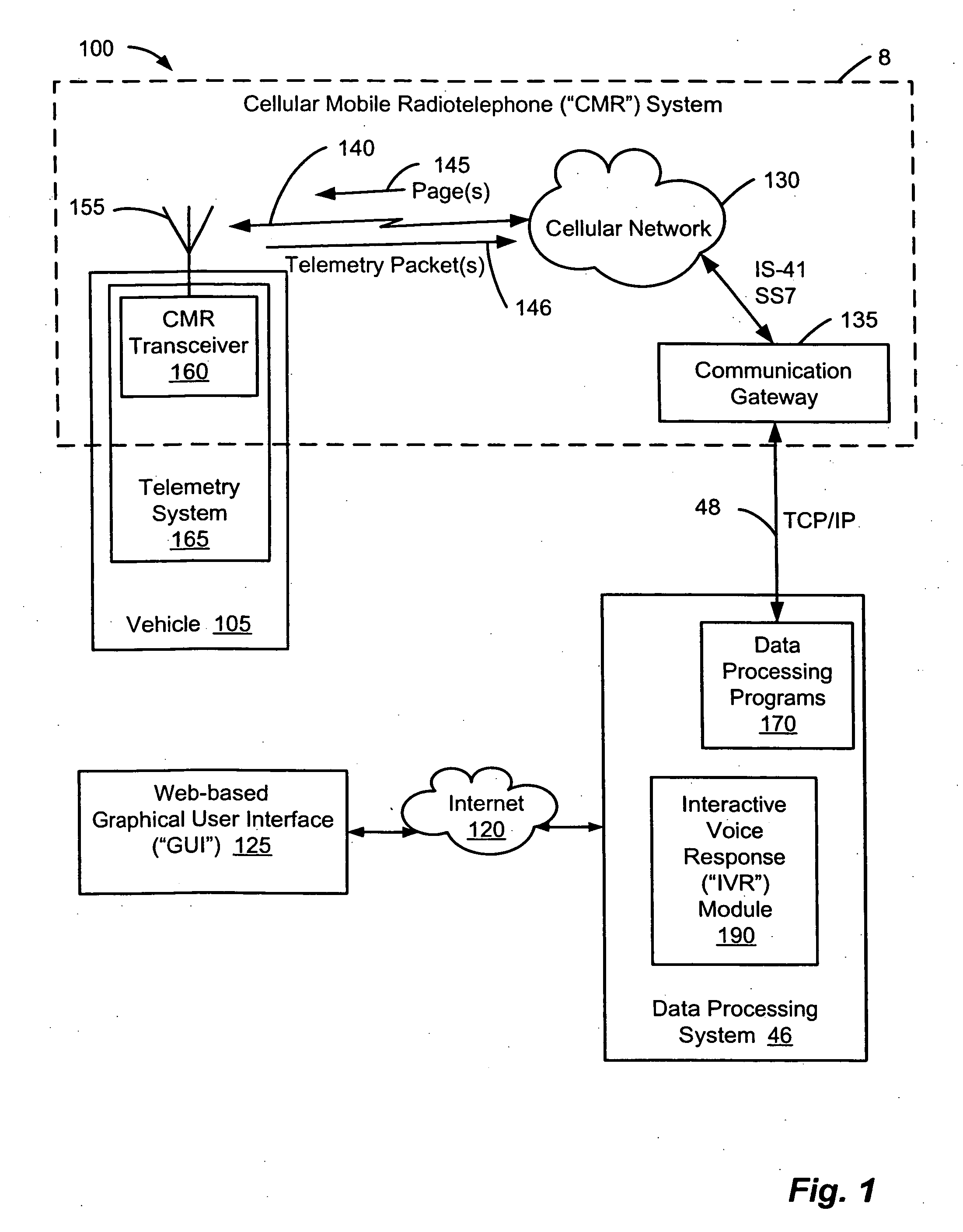
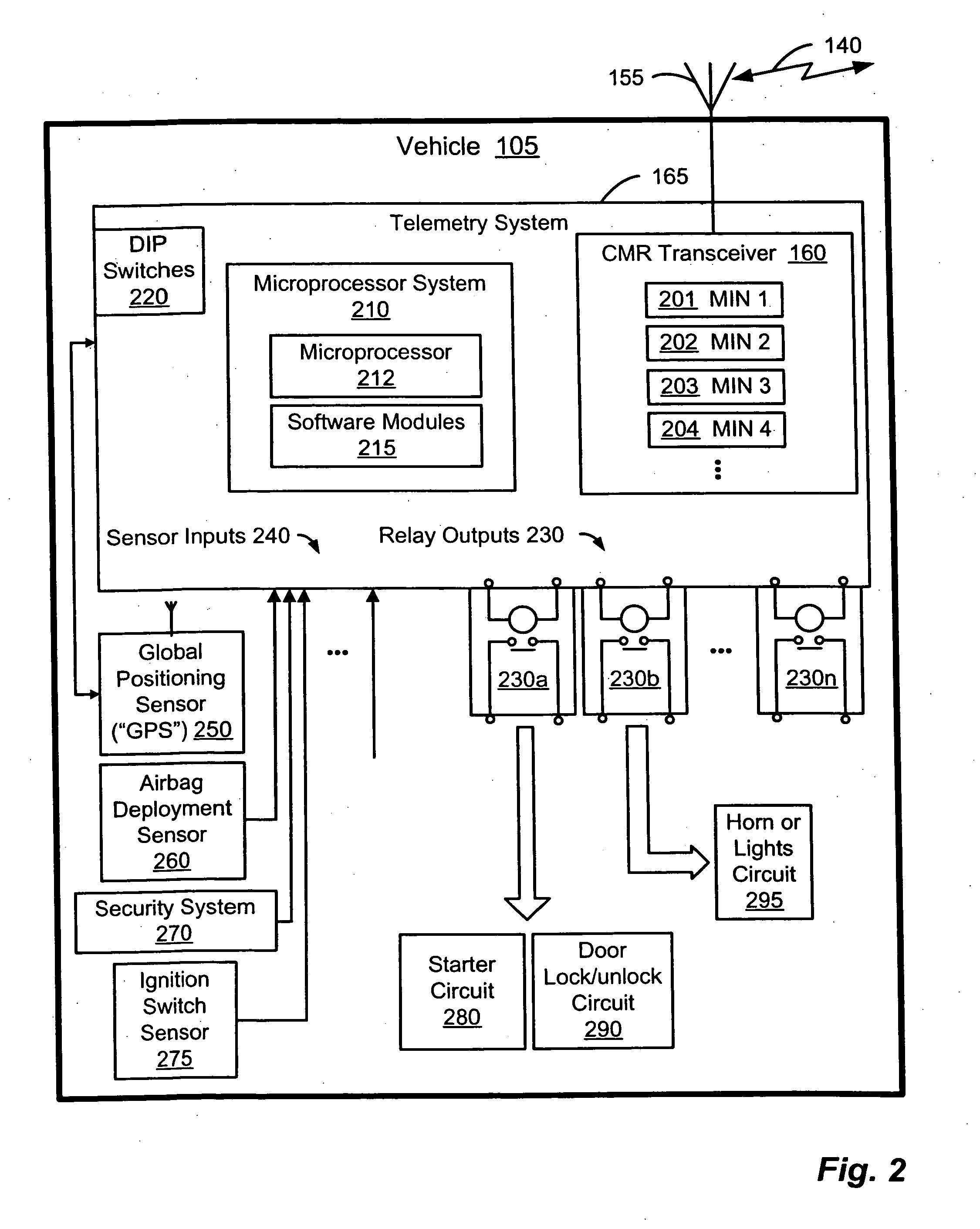
[0046]Exemplary embodiments of the present invention can communicate data, such as bidirectional telemetry messages comprising sensor data or commands, using a plurality of overhead control channels of a wireless communication network. A method and system for communicating wireless communication will now be described more fully hereinafter with reference to FIGS. 1-8, in which embodiments of the present invention are shown. FIGS. 1 and 2 provide block diagram illustrations of an exemplary implementation of a telemetry system coupled to vehicle. FIG. 3 illustrates an exemplary cellular communication system. FIG. 4 illustrates an exemplary communication link based on cellular control channels. FIGS. 5-8 illustrate flowcharts for exemplary processes involving wireless communication in a vehicle telemetry application. FIG. 9 illustrates an exemplary microprocessor system comprising software modules. FIGS. 10-13 illustrate flowcharts for exemplary processes for conserving power consumpti...


PUM


Abstract

A telemetry system coupled to a vehicle can communicate with a remote site using the overhead control channels of a wireless network, such as a cellular mobile radiotelephone network. The telemetry system can monitor or control aspects of the vehicle's operations based on remote user input. The telemetry system can receive a command from a data processing center and, based on the command, perform an action at the vehicle such that a user can remotely interact with the vehicle.

Description

RELATED APPLICATIONS[0001]This application is a divisional of commonly assigned U.S. Nonprovisional patent application Ser. No. 11 / 040,636, now U.S. Pat. No. ______, entitled, “Method and System for Remote Interaction With a Vehicle Via Wireless Communication,” filed on Jan. 21, 2005, which claims the benefit of priority to U.S. Provisional Patent Application Ser. No. 60 / 537,843, entitled “Method and System for Vehicle Recovery and Location Identification” and filed on Jan. 21, 2004. The contents of U.S. Nonprovisional patent application Ser. No. 11 / 040,636, now U.S. Pat. No. ______, and U.S. Provisional Patent Application Ser. No. 60 / 537,843 are hereby incorporated herein by reference.[0002]This application is related to commonly assigned U.S. Nonprovisional patent application Ser. No. 11 / 040,683, entitled “Method and System for Wireless Telemetry,” the contents of which are hereby incorporated by reference.TECHNICAL FIELD[0003]The present invention relates to communicating over a ...

Claims


Application Information

Patent Timeline
Patent Type & Authority Applications(United States)
IPC IPC(8): B60R25/10B60R25/04
CPCB60R25/04B60R25/102B60R25/302B60R25/33H04W52/0274B60R2325/205B60R2325/304H04W52/0251B60R25/403Y02D30/70
Inventor MURRAY, TOMASJANSSON, EDWARD R.
Owner SIERRA WIRELESS AMERICA
Learn More