
SAW filter with an improved attenuation characteristic at a frequency any multiple of an attenuation pole frequency at one or both sides of a pass band

a technology of attenuation characteristic and filter, which is applied in the field of surface acoustic wave filter, can solve the problems of aggravated insertion loss, low quality factor of resonance, and inability to achieve small loss or great attenuation of saw filter, and achieve small insertion loss and great attenuation

Inactive Publication Date: 2005-01-18
INTELLECTUAL VENTURES HOLDING 81 LLC
View PDF6 Cites 17 Cited by
  • Summary
  • Abstract
  • Description
  • Claims
  • Application Information

AI Technical Summary

Benefits of technology

It is an object of the present invention to provide a SAW filter capable of achieving a small insertion loss and a great attenuation and insuring the great attenuation over a broad range up to harmonics, which are any multiple of, e.g. two or three times as high as an attenuation pole frequency at one or both sides of the pass band.

Problems solved by technology

First, the SAW filter cannot achieve a small loss or a great attenuation unless the quality factor of resonance and that of antiresonance of the one-terminal pair SAW resonators are increased.
This, however, lowers the quality factor of resonance and thereby aggravates an insertion loss.
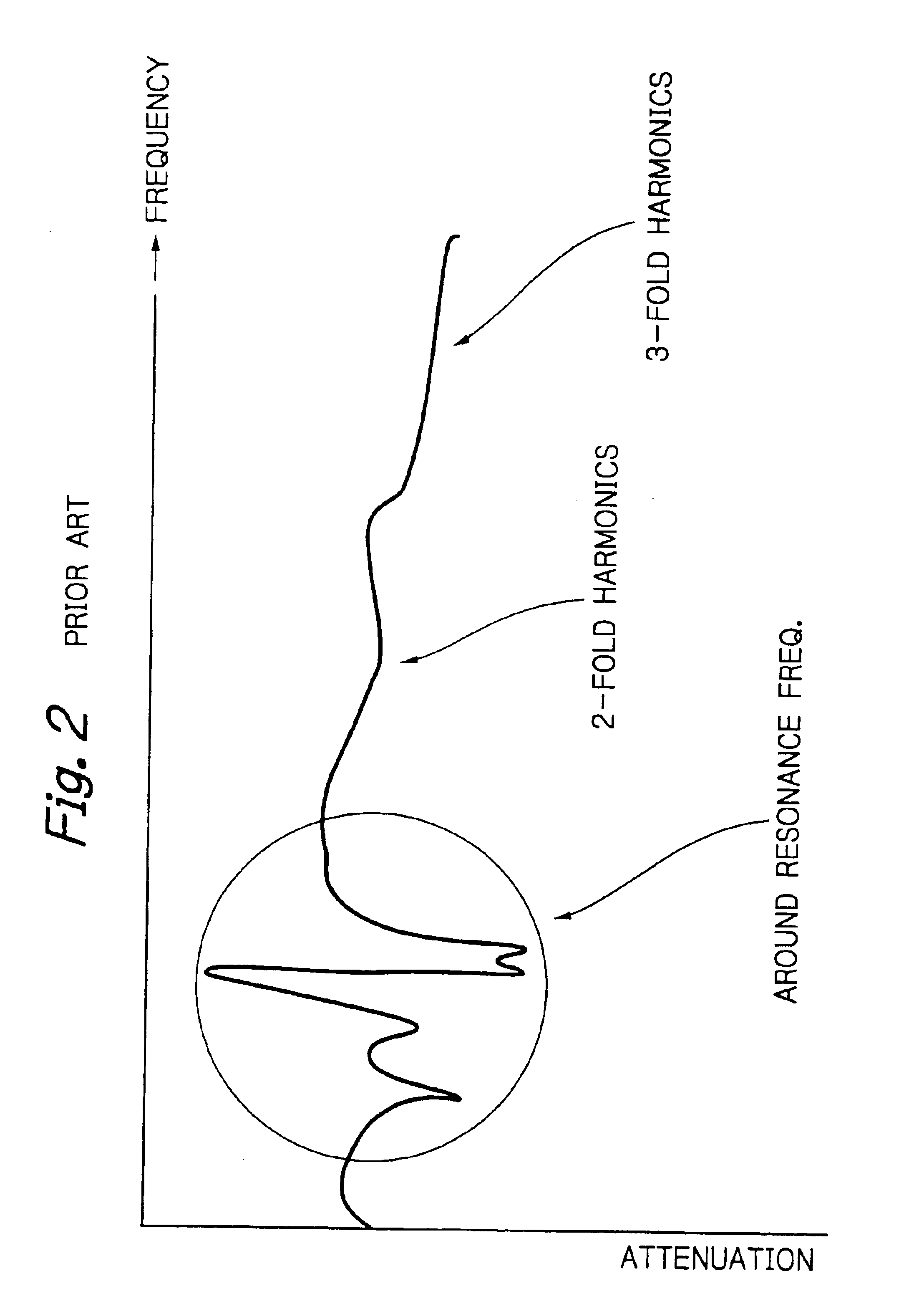
Second, as for a mobile telephone extensively used today, it is necessary to attenuate the secondary and tertiary distortion of a power amplifier included in a transmitter circuit.
Consequently, as shown in FIG. 2, it is difficult to implement a desired attenuation over a broad range up to the harmonics mentioned above.
If additional L and C circuit components are connected to the filter in order to attain the desired attenuation, then the original characteristics in the pass band and attenuation band are also deteriorated because the resonance quality factor of the LC circuit is low.
As stated above, it is difficult to reduce the insertion loss in the pass band while maintaining a great attenuation up to the two- or threefold harmonics of the resonance or antiresonance frequency.

Method used


Image

  • SAW filter with an improved attenuation characteristic at a frequency any multiple of an attenuation pole frequency at one or both sides of a pass band
  • SAW filter with an improved attenuation characteristic at a frequency any multiple of an attenuation pole frequency at one or both sides of a pass band
  • SAW filter with an improved attenuation characteristic at a frequency any multiple of an attenuation pole frequency at one or both sides of a pass band

Examples


Embodiment Construction

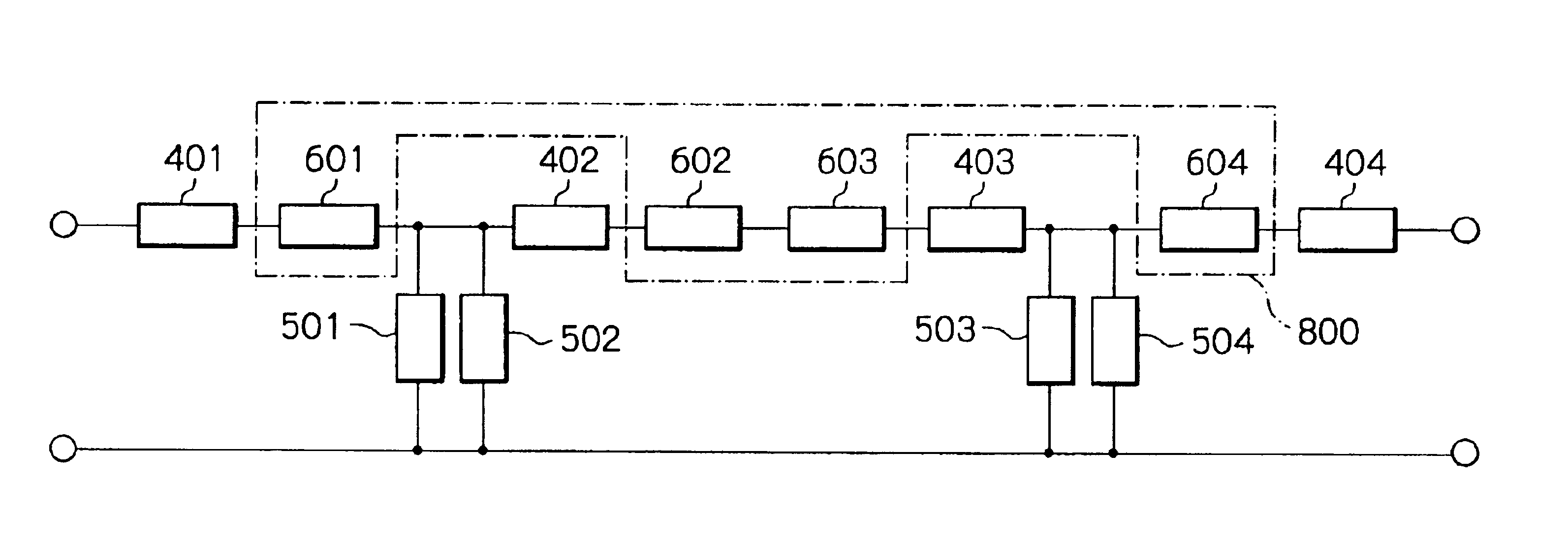
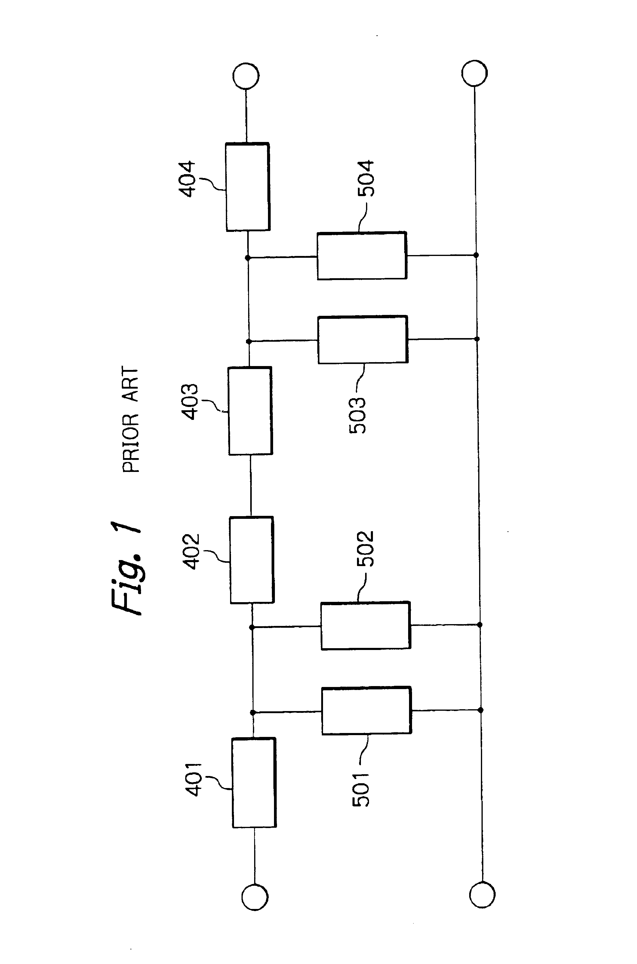
Preferred embodiments of the SAW filter in accordance with the present invention will be described hereinafter. Briefly, the illustrative embodiments to be described each are characterized in that additional resonators are connected to the serial arm resonators or the parallel arm resonators of the conventional, ladder type SAW filter described with reference to FIG. 1.

Referring to FIGS. 3A and 3B, in an embodiment of the SAW filter in accordance with the invention, at any one of the consecutive stages of the SAW filter, an additional resonating device is serially connected to the serial arm resonator. The additional resonating device has its attenuation pole at a frequency that is any multiple of the antiresonance frequency of the serial arm resonator, i.e. an attenuation pole frequency at the higher frequency side with respect to a pass band. The multiple mentioned above may be twice or three times by way of example.

As shown in FIG. 3A, the SAW filter of the illustrative embodimen...


PUM


Abstract

A SAW (Surface Acoustic Wave) filter includes serial arm resonators and parallel arm resonators interconnected in pairs in a multiple-stage, ladder configuration. A resonating device is serially connected to any one of the serial arm resonators and has an attenuation pole frequency higher than that of the serial arm resonator. At the attenuation pole frequency of the serial arm resonator, the resonating device functions as capacitance without performing attenuation. The resonating device has an antiresonance frequency 1.8 times or more but 2.2 times or less, or 2.7 times or more but 3.3 times or less, as high as the antiresonance frequency of the serial arm resonator.

Description

BACKGROUND OF THE INVENTION1. Field of the InventionThe present invention relates to a SAW (Surface Acoustic Wave) filter and more particularly to a SAW filter having an improved attenuation characteristic at a frequency that is any multiple of an attenuation pole frequency at one or both sides of a pass band.2. Description of the Background ArtConventional technologies relating to a SAW filter are disclosed in, e.g. Yoshio Satoh, et al, “A Low-Loss Band-Pass Filter Using SAW Resonators”, Transactions of the Institute of Electronics, Information and Communication Engineers of Japan, Vol. J76-A, No. 2, pp. 245-252 (1993), Mitsutaka Hikita, et al, “Experiments of High-Performance SAW Filters for Mobile Radio Transceivers”, Transactions of the Institute of Electronics, Information and Communication Engineers of Japan, Vol. J76-A, No. 2, pp. 236-244 (1993), and Yuji Suzuki, et al, “Coupled-Mode Theory of SAW Periodic Structures”, Transactions of the Institute of Electronics, Information...

Claims


Application Information

Patent Timeline
IPC IPC(8): H03H9/00H03H9/64
CPCH03H9/6493H03H9/6423
Inventor INOSE, NAOTO
Owner INTELLECTUAL VENTURES HOLDING 81 LLC
Learn More