Explosive detection system

Inactive Publication Date: 2005-01-18
HITACHI LTD
View PDF1 Cites 5 Cited by
  • Summary
  • Abstract
  • Description
  • Claims
  • Application Information

AI Technical Summary

Benefits of technology

An object of the present invention is to provide a transportable explosive detection system using a mass analysis system, and provide a transportable system of low electric power capable of simply moving, rapidly executing a measurement after the movement, and being used with an ordinary home power supply.
A mass analysis system used in the exclusive detection system of the present invention is small-sized and transportable, and it can be used with an ordinary home power supply. In the transportable explosive detection system (hereafter simply referred to as detection system), the electric power is suppressed and start is effected in a short time by first heating an absorption region for absorbing vapor from a detection subject substance, an absorption pipe laying for coupling the absorption region to an ion source, and the ion source with full power, then stopping heating of respective regions, bringing them into a warmth keeping state, and then starting vacuum exhaust devices. Each vacuum exhaust device requires greatest electric power at the beginning of start. In order to suppress the electric power of the whole detection system, a plurality of vacuum exhaust devices used in the detection system are started with start beginning times shifted. In addition, heaters for heating the respective regions are heated again by using left power of vacuum exhaust electric power for driving the vacuum exhaust devices. When the exhaust of the vacuum exhaust devices has reached a stationary state, the absorption region, the absorption pipe laying, and the ion source are heated again. By efficiently controlling the heating of respective regions of the detection system, the start time of the detection system as a whole is shortened.

Problems solved by technology

Furthermore, there is a problem that it is necessary to effect separation by using a gas chromatograph in order to raise the sensitivity and it takes time until detection.
Since all absorbed substances are ionized, however, the ionization efficiency of a specific substance is lowered and the detection sensitivity is low.
Furthermore, there is a problem that separation in the drift tube is difficult and the selectivity is low.
Thus, it is possible to detect at the room temperature plastic explosives, which has been conventionally difficult to detect in the gas state because of its low vapor pressure.
However, the system of the third conventional art has a problem that its application is difficult when detecting a doubtful article or when the necessity of an urgent detection inspection has occurred.
In the case of such detection of a doubtful article, there is a problem that it takes time because vapor is acquired by using a small-sized absorption machine of vacuum cleaner type and measurement is conducted by a system of installation type.
In other words, the merit of the system of installation type that an on-line measurement is possible cannot be made the most of.
However, there is a fear that the highest electric power will be exceeded when measurement start of a mass analysis system, start of an exhaust device and pipe laying heating start are simultaneously executed.
In the case where the above starts are executed simultaneously, therefore, the mass analysis system cannot be used with a typical home power supply.
Since in this case it takes an extremely long time for the pipe laying to arrive at a predetermined temperature as a result of pipe laying heating, the start time as a whole becomes long.
When the pipe laying is heated in the state of the atmospheric pressure, there is a fear that the inside of the pipe laying or the inside of the ion source will be oxidized.
Therefore, the start time becomes long because of heating requiring the longest time.

Method used


Image

  • Explosive detection system
  • Explosive detection system
  • Explosive detection system

Examples


first embodiment

(First Embodiment)

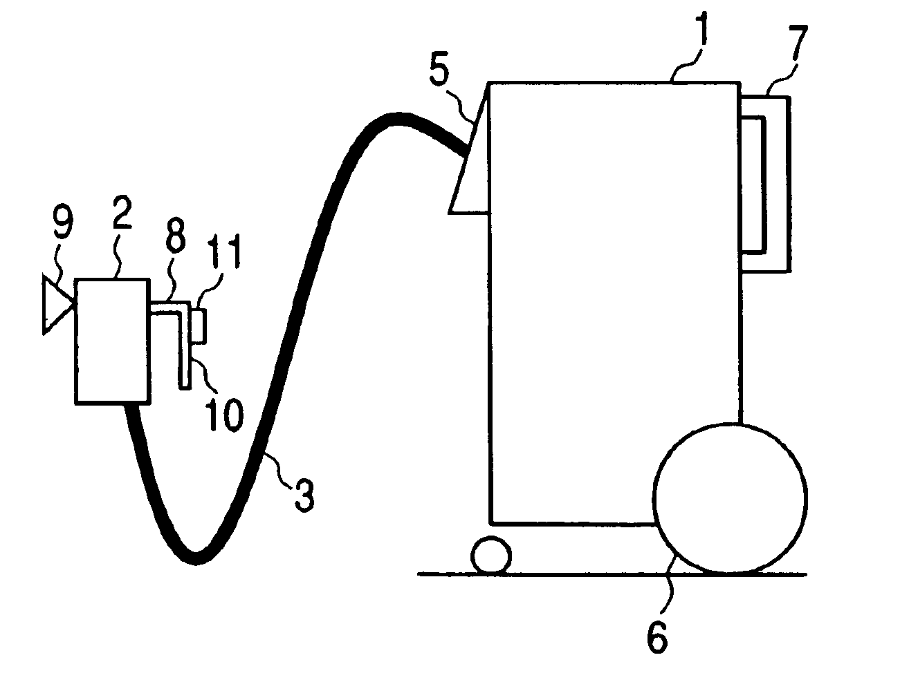
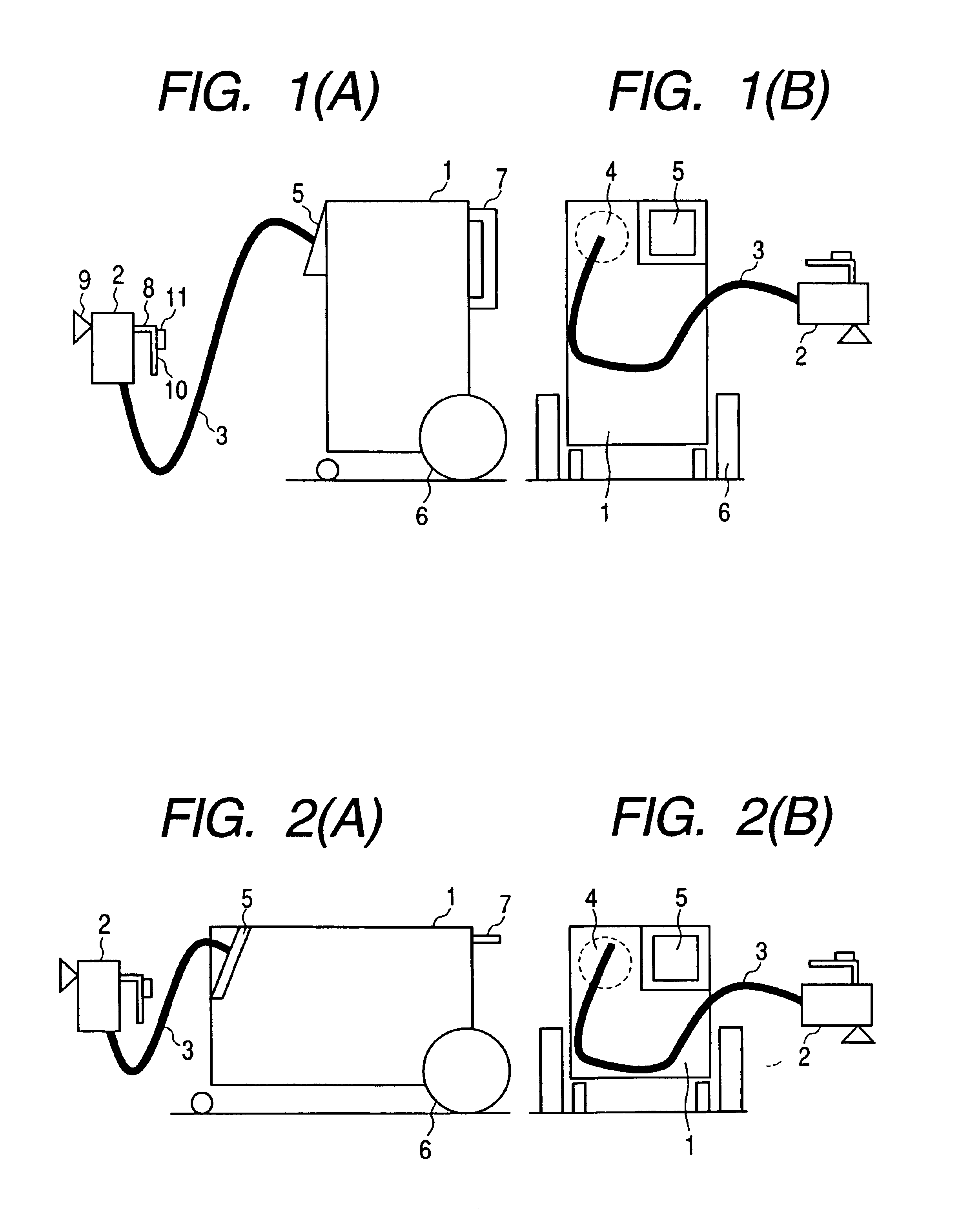
FIGS. 1(A) and 1(B) are diagrams showing an exterior view of a vertical detection system in a first embodiment of the present invention. FIG. 1(A) is a side view, and FIG. 1(B) is a front view. The detection system of the first embodiment includes a system main body (mass analysis system) 1 of the detection system, a mass analysis region 4 disposed in the system main body 1, an absorption region 2 for absorbing and collecting vapor from a detection subject substance, and an absorption pipe laying 3 for supplying vapor of the detection subject substance absorbed by the absorption region 2 to an ion source of the system main body 1.

The system main body 1 has a touch panel control screen 5 or a computer. Respective regions of the detection system are controlled by commands issued from the control screen 5 or the computer. The system main body 1 has a movement tire 6 made of rubber, and the system main body 1 can be moved. The system main body 1 can get over a differen...

second embodiment

(Second Embodiment)

In the first embodiment, heating electric power of the above-stated regions is controlled in current, voltage or electric power. In a second embodiment, the start time is shortened by controlling the heating electric power of the respective regions and thereby increasing the heating efficiencies of the respective regions while suppressing the electric power.

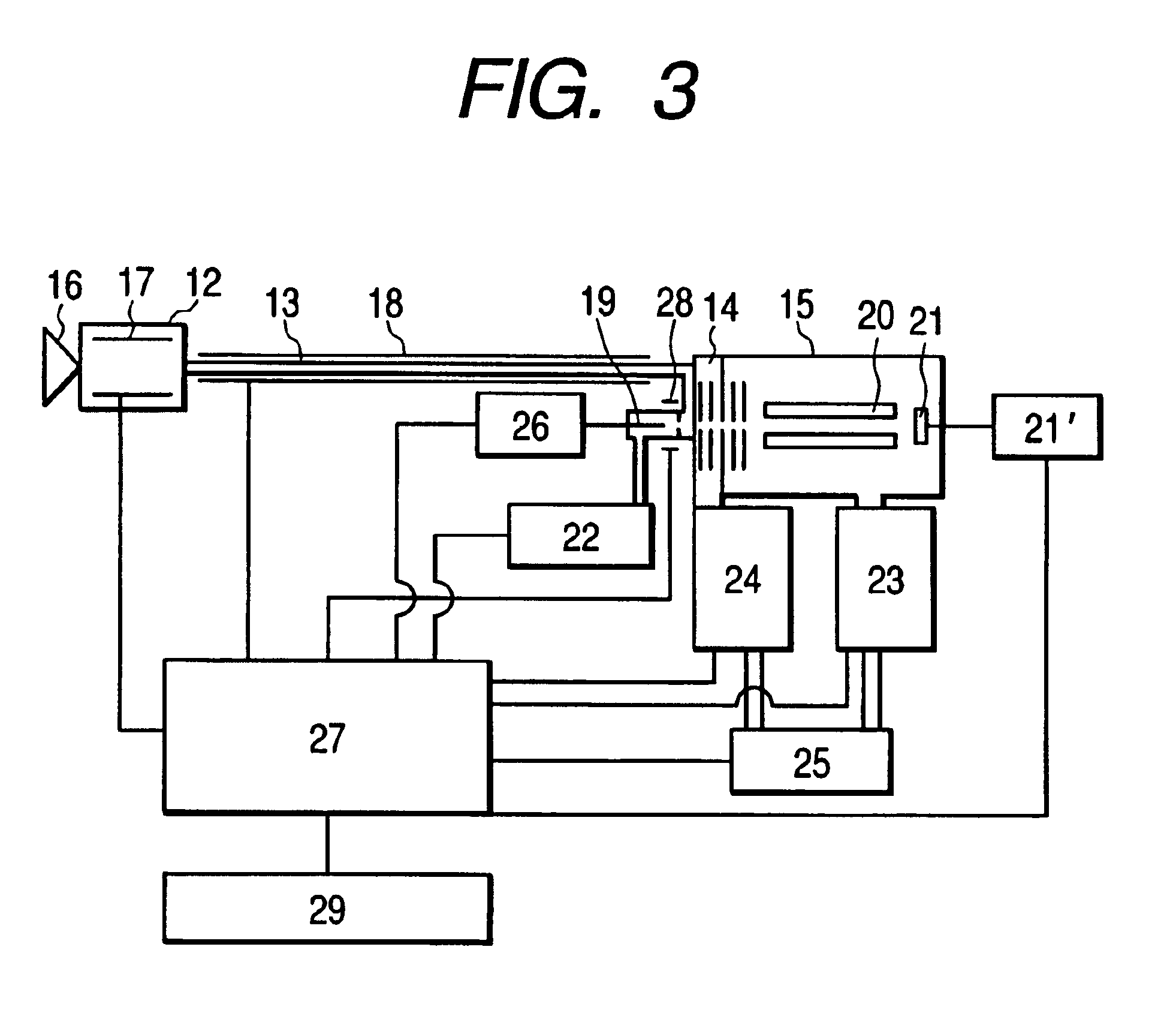
FIG. 6 is a diagram showing an example of a change of electric power in the case where electric power is controlled in the second embodiment of the present invention. Upon beginning of start of the detection system, the controller 27 first consumes electric power mainly. Subsequently, heating of the absorption region heater 17, the pipe laying heater 18, and the ion source heater 28 is started (heating ON). Heating is conducted with full power 100% of a degree that does not exceed the maximum electric power. Heating is temporarily stopped and the warmth keeping state is maintained (heating OFF).

Subsequently, th...

third embodiment

(Third Embodiment)

As described in the first and second embodiments, it takes a longest time in the detection system to heat the heaters 17, 18 and 28 respectively of the absorption region 12, the absorption pipe laying 13, and the ion source 14. In a third embodiment, therefore, the heaters 17, 18 and 28 are always subject to preliminary heating in a state where the detection system is not used and when the detection system is being moved. For example, when the detection system is mounted on a transportation car and transported, the heaters 17, 18 and 28 are always subject to preliminary heating using the electric power of a power supply of the transportation car during the transportation. As a result, the measurement start time of the detection system after the conveyance can be advanced. Power may be supplied from an internal battery or an external battery to the heaters 17, 18 and 28. Since the heaters 17, 18 and 28 are always subject to preliminary heating even in the case where...


PUM


Abstract

An explosive detection system including a sample injection region, an ion source region for generating ions of a sample injected by the ion injection region, a mass analysis region for analyzing mass of the ions, a heater for heating the sample injection region and the ion source region, a plurality of pumps for exhausting a chamber in which the mass analysis region is disposed, and a controller for controlling the regions and the plurality of pumps. The controller conducts control so as to heat the sample injection region and the ion source region with the heaters, then reduce heating electric power supplied to the heaters in order to prevent a predetermined electric power value from being exceeded, and drive the plurality of pumps successively to exhaust the chamber.

Description

BACKGROUND OF THE INVENTIONThe present invention relates to a mass analysis system for detecting explosives, hazardous materials and narcotics.As conventional art methods for effecting detection to determine whether there are explosives, hazardous materials and narcotics, there are chemiluminescence, ion mobility analysis, and mass spectrometry.In the chemiluminescence, subject vapor is picked, temporarily adsorbed on a filter to concentrate. Then the vapor is heated to leave the filter and decomposed by using gas chromatographs, and reacted with a reagent to detect emission of light (first conventional art: U.S. Pat. No. 5,092,155).In the ion mobility analysis, subject gas is absorbed in, adsorbed on a filter to concentrate, and heated to decompose. The subject gas is then ionized with a radioisotope contained in an ion source. The ions are injected into a drift tube, and the mobility of ions is detected (second conventional art: U.S. Pat. Nos. 4,987,767 and 5,109,691).As a highly ...

Claims


Application Information

Patent Timeline
IPC IPC(8): G01N27/62G01N1/22H01J49/04H01J49/02H01J49/00
CPCH01J49/0031
Inventor NAGANO, HISASHITAKADA, YASUAKIWAKI, IZUMIAIKAWA, KOUSHOUTAKIZAWA, MASAYUKIMORISHIMA, SHIGENORI
Owner HITACHI LTD
Why Eureka
Try Eureka