
Nut and method for its fabrication

Inactive Publication Date: 2005-01-18
METALLWARENFAB HERMANN WINKER
View PDF11 Cites 21 Cited by
  • Summary
  • Abstract
  • Description
  • Claims
  • Application Information

AI Technical Summary

Benefits of technology

The object of the present invention thus consists in furnishing a nut of the aforementioned kind as well as a method for its fabrication that is easier and less expensive to produce.
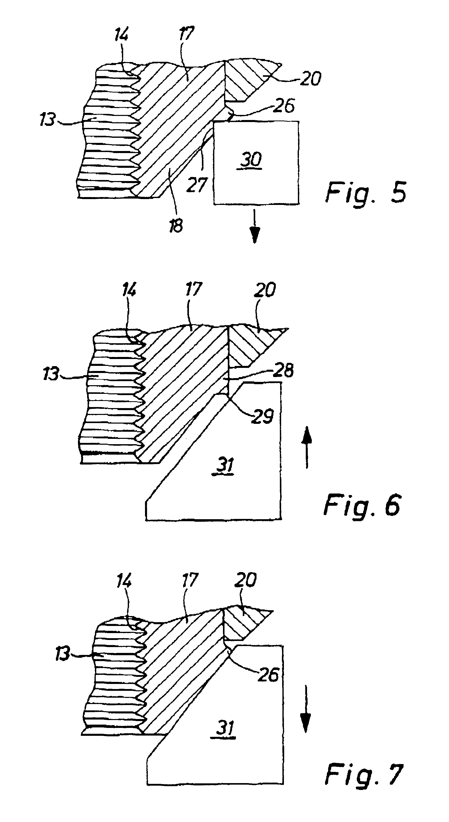
The solution consists of a novel nut, as well as a fabrication method for said nut. The nut according to the invention has only one locking element, namely, a bead arranged on the nut body. This spares at least one lathe procedure, namely, the subsequent machining of the turning plate. The bead can be produced by familiar lathe procedure in the nut body. However, the fabrication method according to the invention calls for the bead to be produced in the nut body by pressing. Thus, the method according to the invention consists only of pressing processes. There is no cutting type machining. Since pressing is substantially less expensive than a cutting type machining, the method according to the invention represents an especially simple, quick and cheap possibility of fabricating such nuts, which is therefore especially suitable for mass production.
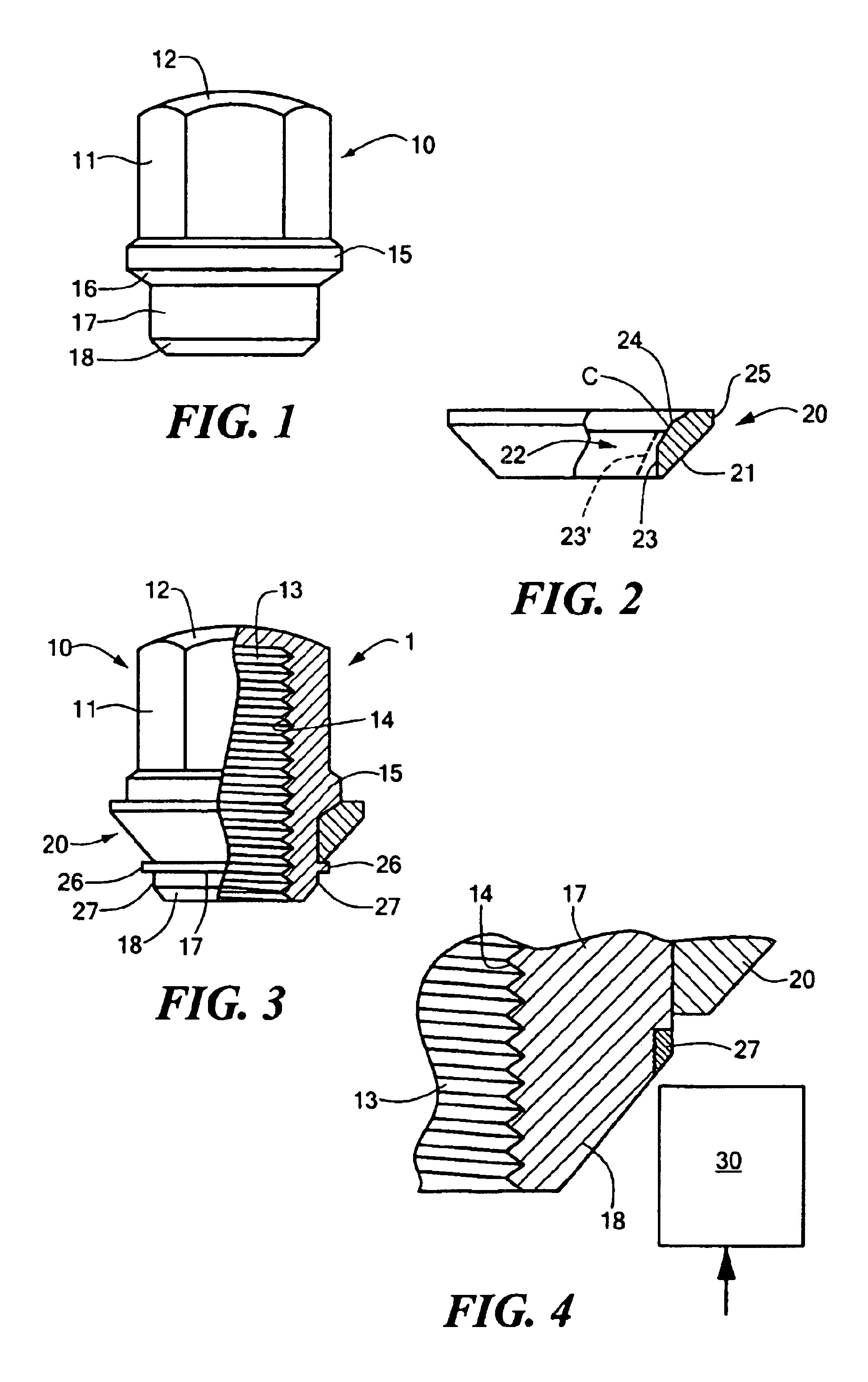
The turning plate preferably has a cylindrical region of surface along its inner surface, which abuts against the neck piece of the nut body. Yet the turning plate can also have a slightly conical surface region along its inner surface. Moreover, it can have a bevel or chamfer at the end of the cylindrical or slightly conical region of surface that is afterwards opposite the base body. This is especially advantageous when the turning plate is shoved onto the nut body after forming the bead. The slightly conical configuration or the bevel or chamfer facilitates the shoving on of the turning plate.

Problems solved by technology

But then the bead must be pressed into the nut body before the coating, or else the surface coating would be damaged and the corrosion protection no longer guaranteed.

Method used


Image

  • Nut and method for its fabrication
  • Nut and method for its fabrication
  • Nut and method for its fabrication

Examples


Embodiment Construction

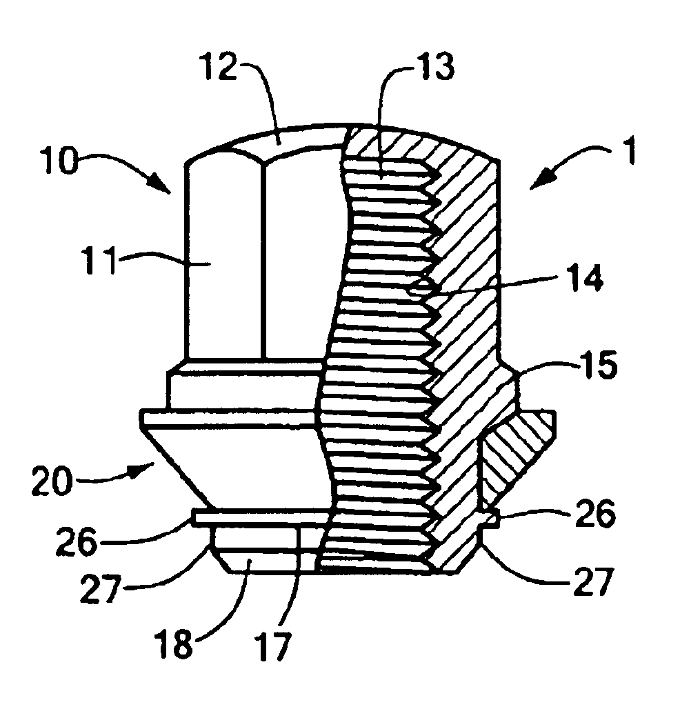
The example of embodiment of a securing nut 1 according to the invention, depicted in FIGS. 1 through 3, serves as a wheel nut for motor vehicles consists of a nut body 10 and a turning plate 20. The nut body 10 has a base body 11, which in the example of embodiment is provided with a cap 12 at the end away from the wheel, The nut body 10, furthermore, has a borehole 13 with an inner thread 14. Of course, it is also possible to omit the cap 12, so that the nut body 10 has a continuous borehole 13. The base body 11 in the example of embodiment has a hexagonal shape for a corresponding wheel wrench; but of course the shape of the base body 11 in this respect can be however desired.

At the end of the base body 11 facing the wheel the nut body 10 has an enlarged shoulder 15 with a conical underside 16, serving as a contact surface for the inner surface of the turning plate 20 (see below). After this conical underside 16 comes a neck piece 17 The neck piece 17 is closed off by a conical s...


PUM


Abstract

The present invention concerns a nut (1) with a nut body (10) having an enlarged shoulder (15) and a turning plate (20) that is rotationally and inseparably arranged on the nut body, wherein the turning plate is shoved onto the nut body and secured by means of a locking element. According to the invention, the locking element is fashioned as a bead (26) provided on the nut body (10), so that the turning plate (20) is arranged between the enlarged shoulder (15) and the bead (26). Moreover, the present invention concerns a method for fabrication of such a nut, wherein the nut body (10) and the turning plate (20) are made by massive forming and, before or after shoving on the turning plate (20), an upsetting (26) is formed by pressing in the nut body (10), or during the fabrication of the nut body (10) a bead (26) is formed as a single piece in the nut body, so that the turning plate (20) is positioned between the enlarged shoulder (15) and the upsetting or the bead (26).

Description

BACKGROUND OF THE INVENTIONThe present invention concerns a nut, as well as a method for its fabrication, the nut being of the type comprising a nut body and a turning plate, the nut body having an enlarged shoulder, the turning plate being capable of rotating and being inseparably arranged on the nut body, the turning plate being shoved onto the nut body and secured by means of a locking element.A nut of this kind is known from DE 3,325,255 02. This publication discloses a wheel nut of metal or a metal alloy for utility vehicles with a nut body and a turning plate fashioned as a pressing plate. The turning plate is shoved onto the nut body and anchored so that it can easily turn on the nut body, but cannot be stripped off. This is assured by locking means, which are provided on the outer circumference of the nut body and on the inner circumference of the pressing plate and which engage with each other so that the turning plate is inseparably connected to the nut body. These locking...

Claims


Application Information

Patent Timeline
IPC IPC(8): B21K25/00B21K1/70B21K1/00B60B3/00B60B3/16F16B39/26F16B39/00
CPCB21K1/70B21K25/00F16B39/26B60B3/16B60B3/145
Inventor WINKER, ALEXANDER
Owner METALLWARENFAB HERMANN WINKER
Learn More