Eureka AIR delivers breakthrough ideas for toughest innovation challenges, trusted by R&D personnel around the world.

Intervention device for a subsea well, and method and cable for use with the device

a technology for drilling wells and interventions, which is applied in the direction of earthwork drilling and mining, drilling machines and methods, and fluid removal. it can solve the problems of large equipment and material investment, high cost of intervention, and loss of human lives, and achieve the effect of simple type of sealing means

Inactive Publication Date: 2005-01-18
FMC KONGSBERG SUS
View PDF19 Cites 81 Cited by
  • Summary
  • Abstract
  • Description
  • Claims
  • Application Information

AI Technical Summary

Benefits of technology

Another important advantage of the invention is that the vessel, to some extent, may be drifted by the weather and wind and, thereby, be adjusted to the varying conditions at the surface. The vessel may drift as far away as permitted by the length of the cable and / or umbilical.
is that the vessel, to some extent, may be drifted by the weather and wind and, thereby, be adjusted to the varying conditions at the surface. The vessel may drift as far away as permitted by the length of the cable and / or umbilical.
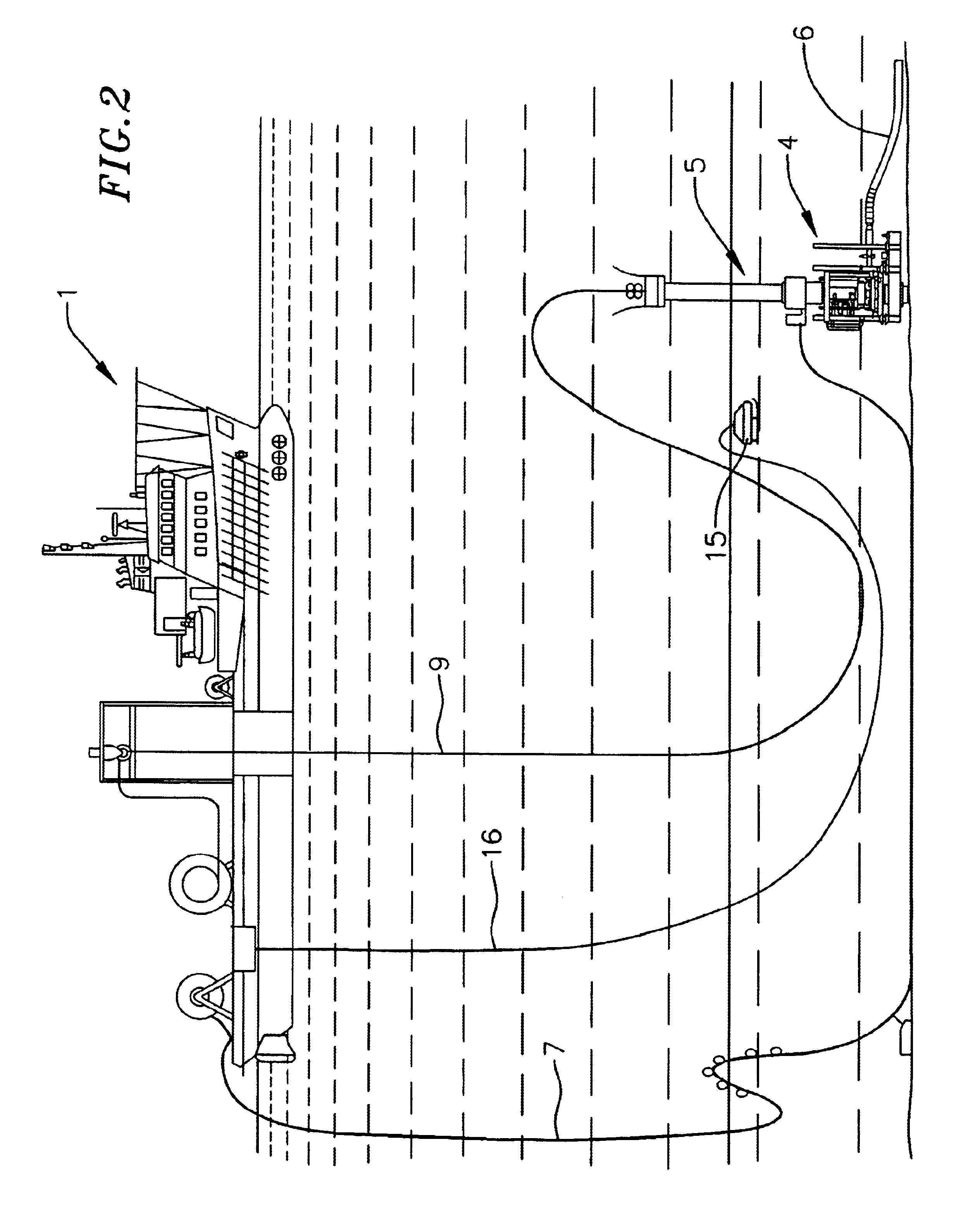
Another great advantage of the invention is that different lengths of the cable and umbilical may be present in the sea. For example, during a situation in which the cable has to be cut, it will normally be sufficient of time to close all of the valves, detach the umbilical from the seabed in a controlled manner and withdraw this to the vessel. Vice versa, if the umbilical has a defect or has to be cut (involving that all of the valves in the lubricator and well have to be closed), it will normally be sufficient of time to withdraw the cable slack before this is cut.
The cable may readily be fished out by means of a ROV, and the work continued when the dangerous situation has been remedied.
One particular advantage of the invention is that a light vessel may be used. When the injector is used together with the preferred lubricator, the unwanted fluids may be circulated in the well, as discussed in NO Patent No. 309439. This might result in great savings, as there is no need of large and heavy equipment for the treatment of the hydrocarbons on the vessel.
Moreover, the cable may be provided with friction at the same level as a string and, therefore, the use of a more simple type of sealing means is enabled.

Problems solved by technology

If an uncontrolled blowout should occur, the vessel may lose buoyancy due to the gas flowing to the surface from the well, resulting in loss of human lives.
Another disadvantage of this position involves that the vessel must be provided with heave compensator means to balance wave motions during the operation.
The disadvantage is that this intervention type is very expensive as the use of a drilling rig is required.
Because of the spaces between the wire components, the disadvantage of the wire is that a particular injector for grease (so-called “grease injector head”) must be used, by which grease under pressure is continuously injected to seal around the wire.
Even if the grease provides relatively low friction and enables lowering of the tool by its own weigth, this method requires large investments for equipments and materials, in particular grease.
Therefore, large quantities of grease are consumed during this procedure.
As a result, the vessel has to be relatively large (and thereby expensive) due to all of the equipment located on the vessel.
However, a disadvantage of the previous stuffing box types is that the providing of such a sealing around the string may result in a too large friction.
Another disadvantage is that such strings have a limited strength, and also a limited usability as power supply or signal transmission means are not included.

Method used


Image

  • Intervention device for a subsea well, and method and cable for use with the device
  • Intervention device for a subsea well, and method and cable for use with the device
  • Intervention device for a subsea well, and method and cable for use with the device

Examples


Embodiment Construction

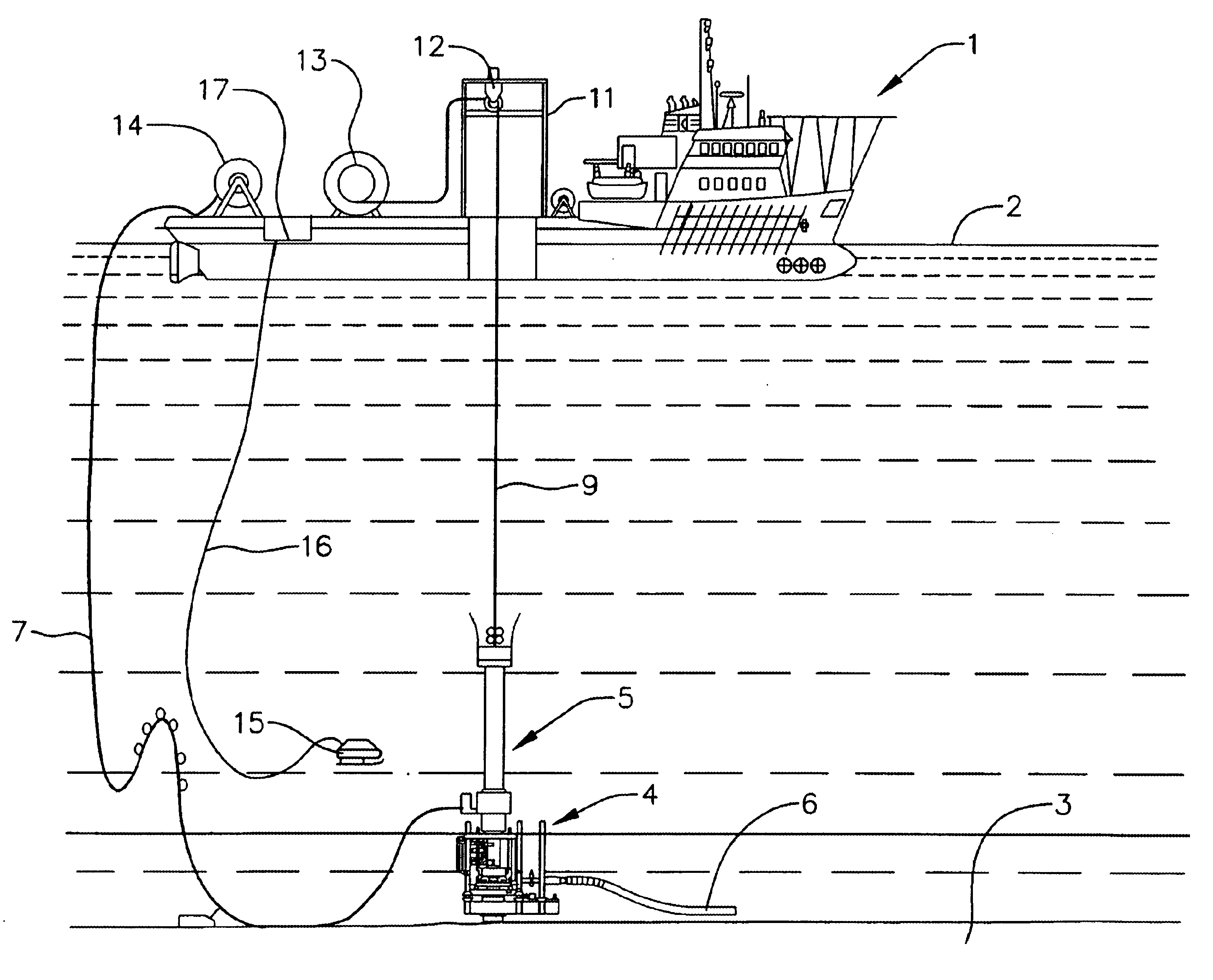
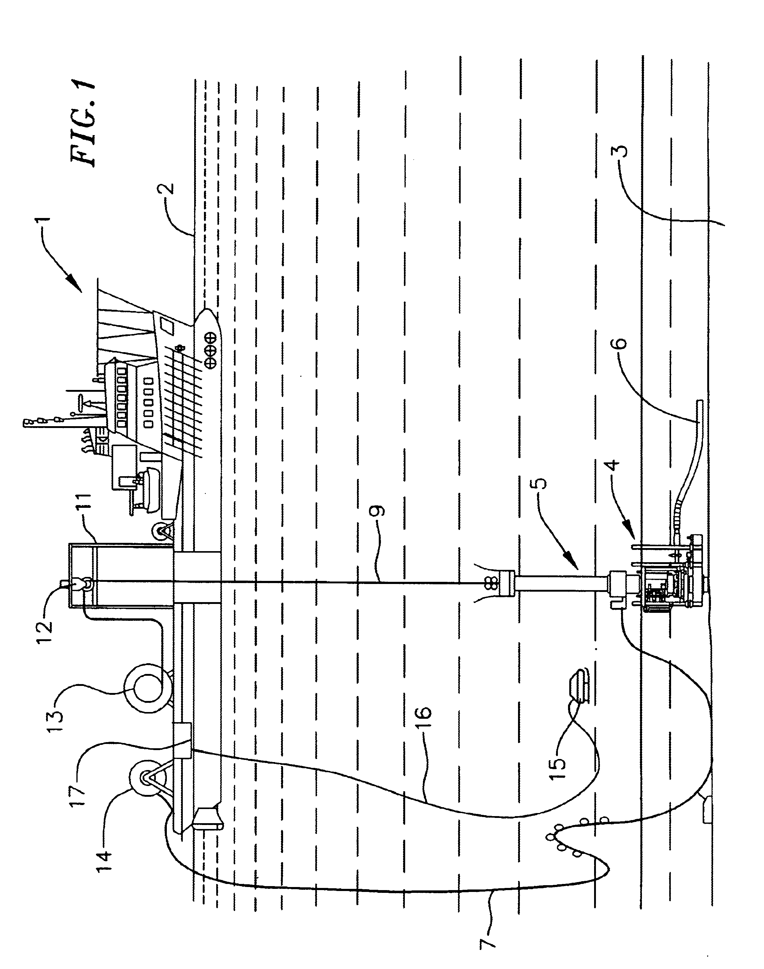
In FIG. 1 is shown a vessel 1 floating on a mass of water 2. The vessel has various equipment for controll, measurements, etc. well known in the field. In particular, the vessel is provided with heave compensator means and dynamic positioning (DP) means to keep the vessel in a correct position.

A Christmas tree 4 for a well 10 is situated at the seabed 3, which Christman tree is completed and made ready for production in accordance with standard practice. Produced oil and / or gas flowing upwards from the well is led through a pipeline 6 to a production facility, such as a production vessel.

The vessel includes a tower 11 comprising a drive mechanism 12 for cable 9. The drive mechanism may be a motor-driven drum, which may unwind or wind the cable, although an injector located on the tower 11 is preferred, as indicated in FIG. 1.

Moreover, storing means 13 for a tool cable 9, and a storing drum 14 and storing drum 17 for an umbilical 16 and umbilical 7 for a subsea robot (ROV) 15, respec...


PUM


Abstract

A device for intervention of a subsea oil and / or gas well by means of a tool (8) suspended by a cable (9), fed from or withdrawn to a vessel (1) and driven by a drive mechanism (12) located on the vessel. The device comprises a lubricator (5) having a tool housing for the insertion of the tool into the well, and a stuffing box (40) sealing around the cable after the tool is inserted into the well. According to the invention an injector which drives the cable in the well is located on the lubricator, and is controllable independently of the drive mechanism for the cable located on the vessel. The drive mechanism and the injector may be synchronized in a manner, among others, providing that the cable is hanging in a predetermined arc during the intervention, whereby the vessel may be moved from the well. Moreover, the invention relates to a method and a cable used together with the device.

Description

FIELD OF THE INVENTIONThe invention relates to a device for intervention of a subsea well by means of a tool or the like suspended by a cable, fed from, respectively withdrawn to a vessel or the like, and driven by a drive mechanism located on the vessel, said device comprising a lubricator adapted to be located at a subsea Christmas tree in the well, and having a tool housing, for the insertion of the tool into the well, and sealing means, which encloses the cable in a slidable and sealed manner after the tool is inserted into the well.Moreover, the invention relates to a method and a cable for use together with the device.BACKGROUND OF THE INVENTIONWorks are performed in an oil or gas well to stimulate or treat the well, whereby the production is increased, to replace various equipment such as valves, to make measurements, to monitor the state of the well, or anything else being required.Treatment of the well to increase the production rate or volume is made after a cost / benefit e...

Claims


Application Information

Patent Timeline
Patent Type & Authority Patents(United States)
IPC IPC(8): E21B19/22E21B19/00E21B33/03E21B33/076
CPCE21B19/002E21B7/124E21B33/076E21B19/22
Inventor CARLSEN, HANS-PAUL
Owner FMC KONGSBERG SUS
Why Eureka
Eureka Blog
Learn More