
Data exchange between users connected by a bus system and having separate time bases

a bus system and data exchange technology, applied in the field of data exchange, can solve the problems of reducing and related art being unable to deliver optimal, so as to achieve greater tolerance of accuracy and increase the efficiency of bus capacity utilization

Inactive Publication Date: 2005-01-11
ROBERT BOSCH GMBH
View PDF14 Cites 119 Cited by
  • Summary
  • Abstract
  • Description
  • Claims
  • Application Information

AI Technical Summary

Benefits of technology

[0011]Therefore, compared to the related art, the present invention advantageously includes a higher protocol layer with respect to the actual bus (CAN) protocol which is retained unchanged within the framework of the time-controlled communication according to the present invention. Thus, the time-controlled communication advantageously allows full capacity utilization of the bus, and at the same time makes it possible to hold the latency times for each message to a defined value.
[0018]Another advantage is that, because of this, the clocks in the individual stations can exhibit a greater tolerance of accuracy (cheaper components, particularly oscillators) between the synchronization intervals.
[0019]Expediently, the first cycles or base cycles (interval between two reference messages) can become greater, resulting in a rise in efficiency of the bus capacity utilization.
[0020]It is also advantageous that the length of a base cycle is no longer limited by the tolerance of the individual clocks, and that the intervals between the individual messages (so-called inter-frame gaps), necessary in other methods to compensate for tolerances, may be omitted.

Problems solved by technology

Thus, the bus is frequently not completely utilized to capacity.
Because of this, intervals are frequently necessary between individual messages to compensate for tolerances, thus reducing the efficiency of the bus capacity utilization.
It is apparent that the related art is unable to deliver optimal results in every respect.

Method used


Image

  • Data exchange between users connected by a bus system and having separate time bases
  • Data exchange between users connected by a bus system and having separate time bases
  • Data exchange between users connected by a bus system and having separate time bases

Examples


Embodiment Construction

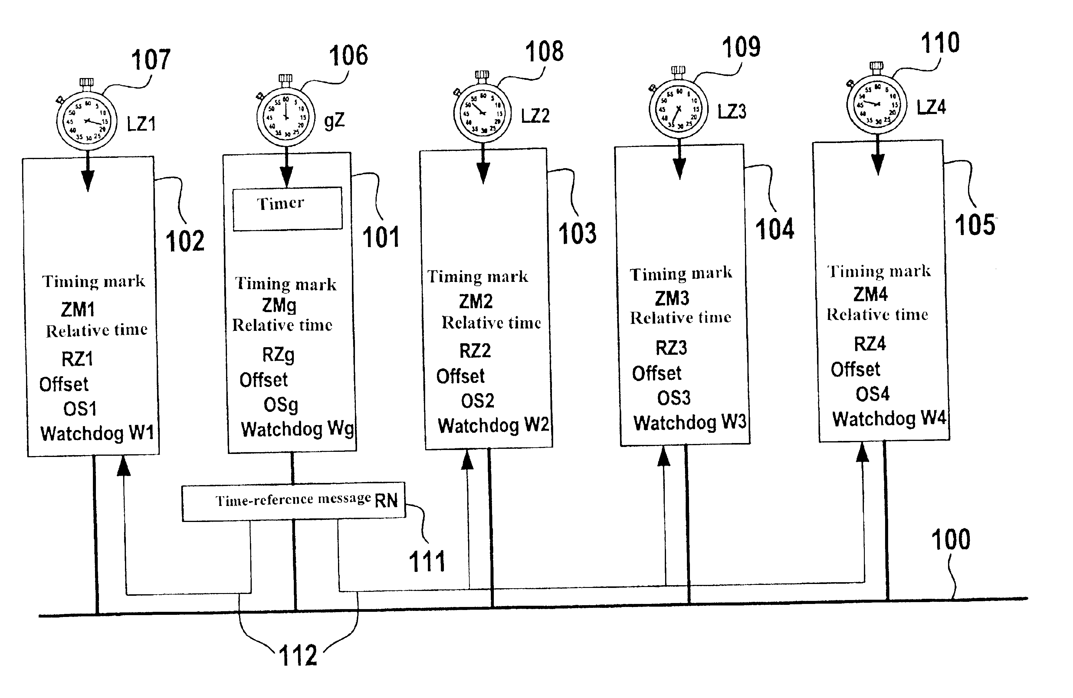
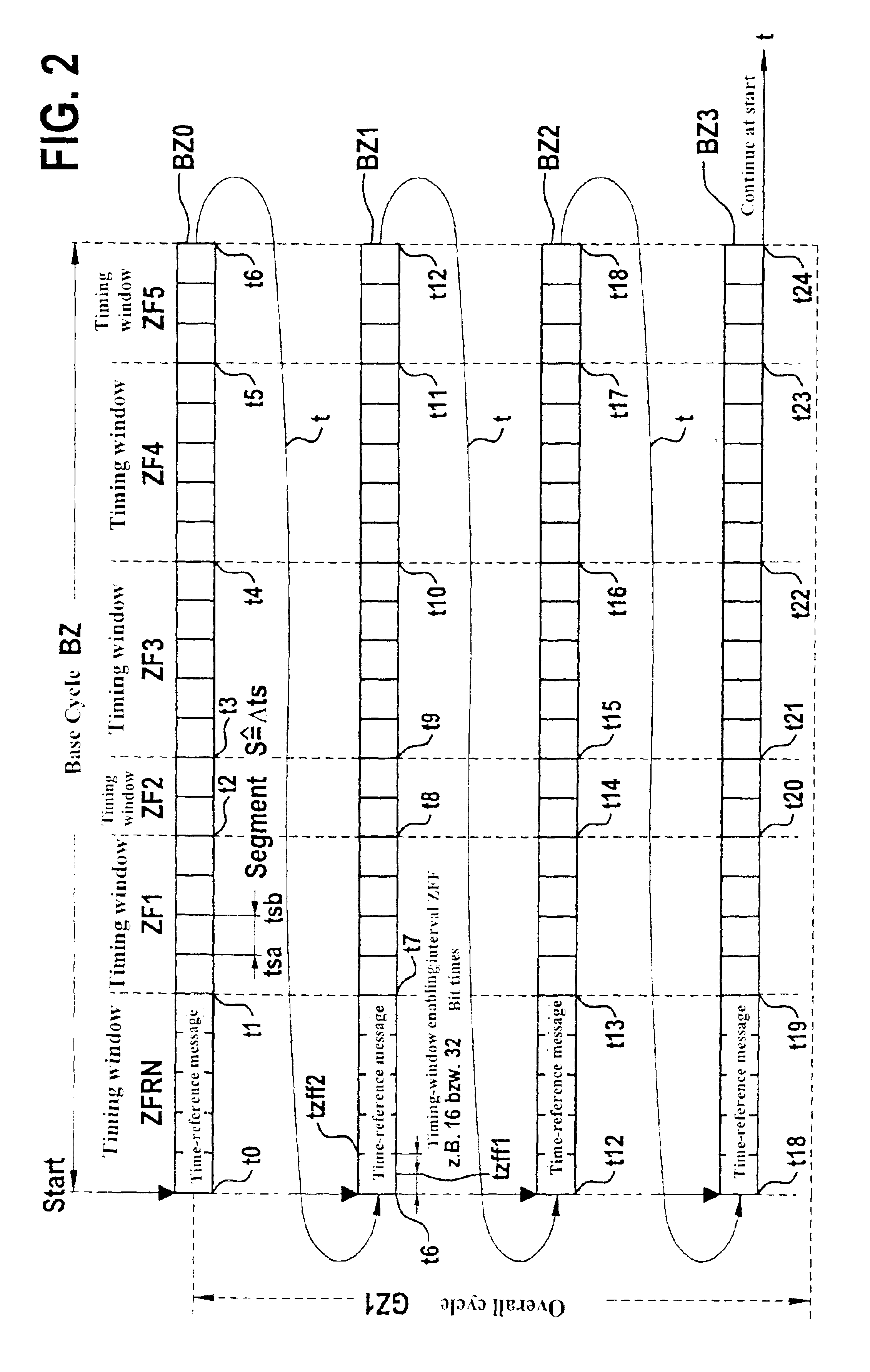
[0027]TTCAN is based essentially on a time-controlled, periodic communication which is clocked by a timer (node, user) with the aid of a time-reference message, or reference message RN for short. The period up to the next reference message RN is denoted as base cycle and is subdivided into n timing windows (see FIG. 2). Each timing window allows the exclusive transmission of one periodic message of variable length. These periodic messages are transmitted in a TTCAN controller by using timing marks which are coupled to the expiration of a logical relative time. However, TTCAN also allows the consideration of vacant timing windows. These timing windows can be used for so-called spontaneous messages, the access within these timing windows to the bus being utilized via the arbitration scheme of CAN (arbitrating messages). The synchronization of the timer clock (global time gZ) with the internal local time of individual nodes lZ1 through lZ4 is taken into account and efficiently converte...


PUM

PropertyMeasurementUnit
Lengthaaaaaaaaaa
Timeaaaaaaaaaa

Abstract

A method and device for the exchange of data in messages between at least two users which are connected by a bus system and have separate time bases, the messages containing the data being transmitted by the users via the bus system; and a first user, in a function as timer, controls the messages as a function of time in such a way that it repeatedly transmits a reference message, which contains time information regarding the time base of the first user, via the bus at a specifiable time interval; the at least second user forms its own time information, using its time base, as a function of the time information of the first user; a correction value is ascertained from the two pieces of time information; and the second user adapts its time information and / or its time base as a function of the correction value.

Description

FIELD OF THE INVENTION[0002]The present invention relates to a method and a device for the exchange of data between at least two users (nodes) connected to a bus system.BACKGROUND INFORMATION[0003]As related art in automotive networking, the CAN (controller area network) protocol has been used for several years. In that case, the communication is controlled in an event-driven manner. Very great loads can be produced when the transmission of various messages is to be initiated at the same time. The non-destructive arbitration mechanism of CAN guarantees the sequential transmission of all messages according to the priority of their identifiers or identifications. For hard real-time systems, an analysis of the transit times and bus loads for the entire system must be made in advance, to make sure that all message deadlines can be observed (even under peak load).[0004]There are already communication protocols which are based on time-controlled processing, such as TTP / C or Interbus-S. Th...

Claims


Application Information

Patent Timeline
IPC IPC(8): G06F1/14G06F13/00H04J3/06H04L7/00H04L12/417
CPCB01D45/04G05B2219/25031H04J3/0655
Inventor WEIGL, ANDREASFUEHRER, THOMASMÜLLERHARTWICH, FLORIANHUGEL, ROBERT
Owner ROBERT BOSCH GMBH
Learn More