
Reciprocating device and linear suspension

a reciprocating device and linear suspension technology, applied in the direction of spring/damper functional characteristics, machines/engines, shock absorbers, etc., can solve the problems of vibration and failure, inducing torsional motion, fretting on the end of flexure elements, etc., to simplify the mechanical coupling structure, reduce fretting, and prolong the life

Inactive Publication Date: 2005-01-11
RIX INDS
View PDF14 Cites 6 Cited by
  • Summary
  • Abstract
  • Description
  • Claims
  • Application Information

AI Technical Summary

Benefits of technology

"The invention provides an improved linear suspension element and a reciprocator using the linear suspension element. The suspension element reduces fretting, simplifies the mechanical coupling structure, provides longer life, and maximizes stroke within allowable stress limits. The suspension element also provides a mechanism for aligning parts by directly engaging features of the drive mechanism. The linear suspension element includes a mount and a plurality of legs each having a first portion for coupling to the moving element, a second portion coupled to the mount, and a third portion engaging the linear drive mechanism. The legs also have preloads. The foregoing and other features and advantages of the invention will be apparent from the following more particular description of preferred embodiments of the invention."

Problems solved by technology

A problem with spiral suspensions is their inducement of a torsional motion about the reciprocation axis.
This motion may cause vibration and failure and requires the moving element to be circular in section, or have excessive clearances to the stationary elements of an assembly in order not to collide with the stationary elements during operation.
A potential problem with these suspensions, however, is that fretting may occur on the ends of the flexure elements where they are clamped, especially at large strokes and strap strains.
Furthermore, the clamping of the legs to the mount may be mechanically cumbersome.
Such alignment features are expensive to add as they require high precision in both hole-making and in fastener dimensions, as well as precision in location of the aligning features with respect to the features to be aligned (e.g., magnets, stator pole faces, etc.).
Further, the attachment of the suspension must not allow local relative motion between the suspension and its mounts, or fretting damage to that interface can occur, leading to premature failure of the suspension.
Additional complexity is created where multiple suspension elements are fitted in parallel, and it becomes necessary to align the elements in both centric and angular manners.
In devices like those of Redlich, U.S. Pat. No. 4,602,174, or Bhate, U.S. Pat. No. 4,349,757, the radial laminations of the stator make this an awkward and expensive mounting, as axial holes can only be provided in auxiliary rings separately attached to the radial laminates.

Method used


Image

  • Reciprocating device and linear suspension
  • Reciprocating device and linear suspension
  • Reciprocating device and linear suspension

Examples


first embodiment

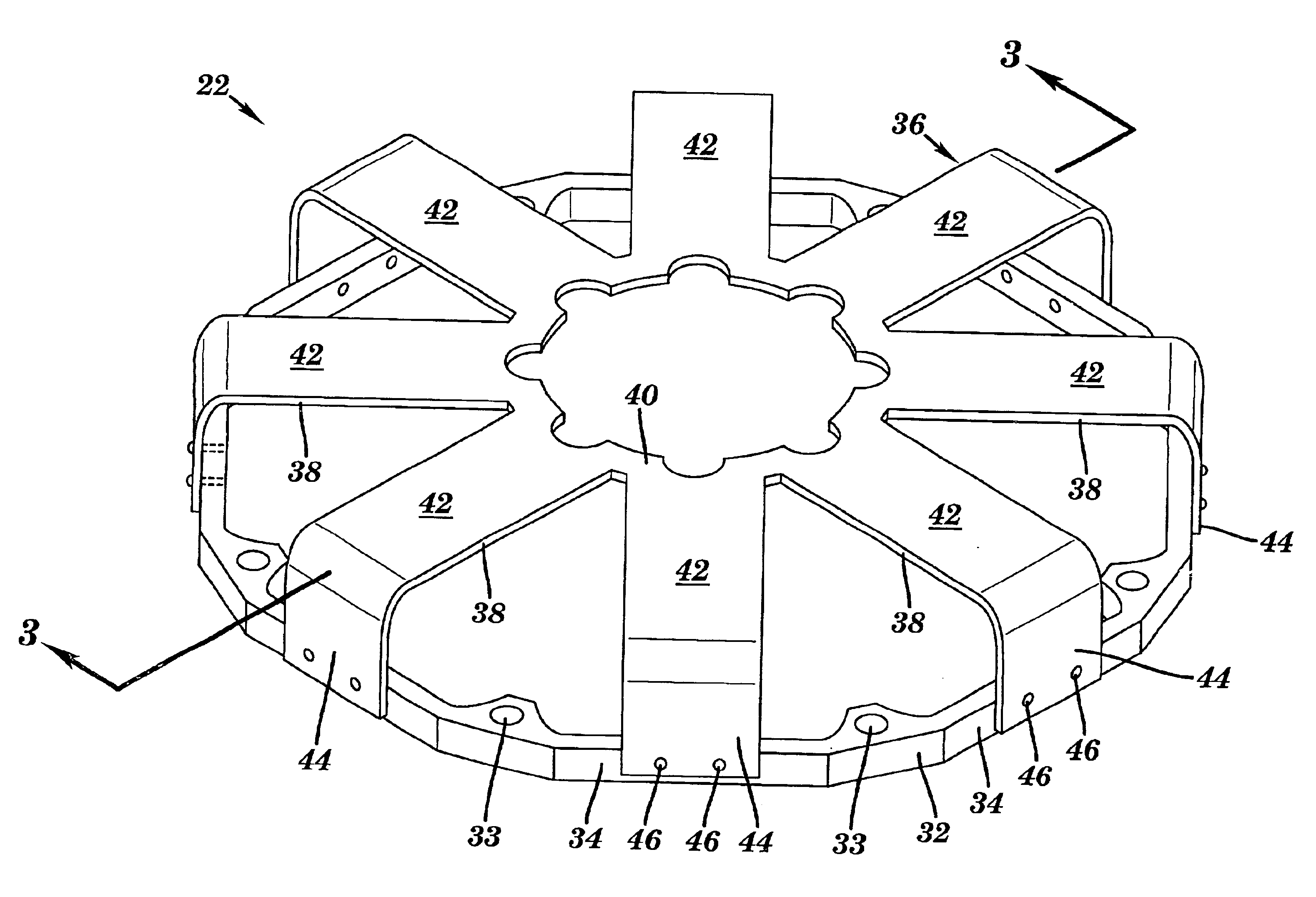
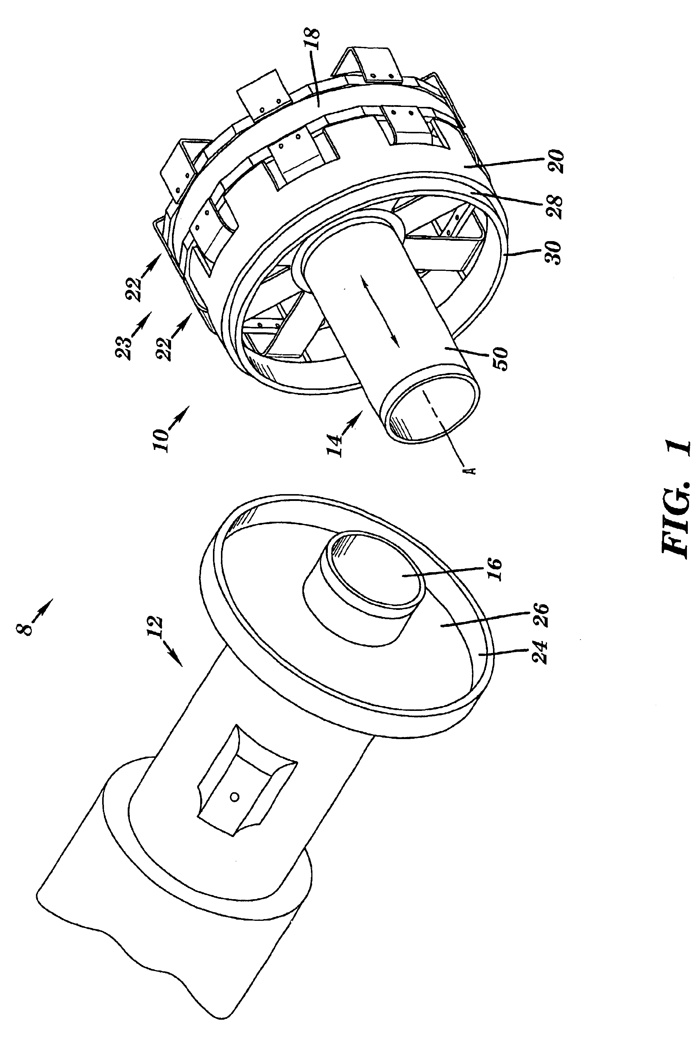
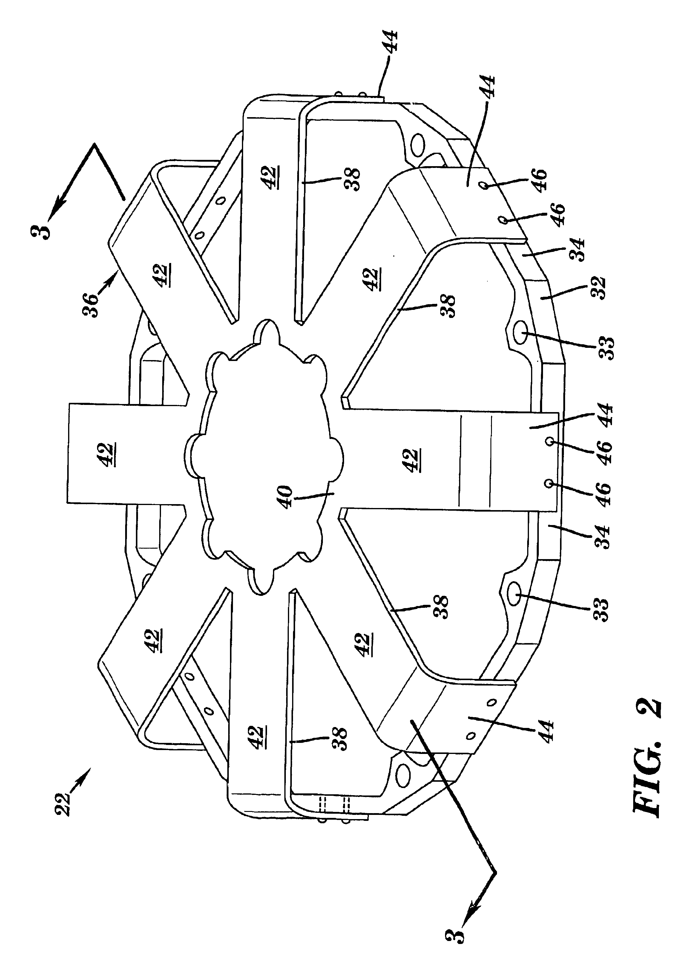
Referring to FIG. 1, a reciprocator assembly 8 is shown that includes a reicprocator 10 and a mating cylinder assembly 12. In operation, reciprocator 10 and cylinder assembly 12 are assembled such that a moving element 14 of reciprocator 10 is linearly movable along an axis A of reciprocator 10 and in a close-clearance relation in a cylinder bore 16 of cylinder assembly 12. Reciprocator 10 includes moving element 14 and a linear drive mechanism or motor 18, similar to that disclosed in U.S. Pat. Nos. 5,389,844 and 5,139,242, which are hereby incorporated by reference. Reciprocator 10 may also include a reciprocator casing 20, sometimes called a crown ring. Linear drive mechanism 18 includes, as will be recognize by one with skill in the art, a plunger and stator and has at least one, and preferably two, linear suspension elements 22 that form a linear suspension 23 coupled thereto. Linear suspension 23 allows reciprocation and substantially restricts non-axial motion, e.g., torsiona...

second embodiment

Referring to FIGS. 11-15, another embodiment of the invention is illustrated. In any reciprocating device, there is a need to restrain the moving element to its intended axis of motion, while minimizing friction or drag associated with that restraint. Forces tending to move the reciprocating part (moving element or plunger) from its intended axis include magnetic side pull, drive force non-axiality, inertial reaction to housing motions, and non-uniform gas pressures or flows. In addition, many such devices must operate with little or no lubrication for applications where lubricant is undesirable. In such cases, ordinary sliding bearings are generally unsuitable because of wear, or lubricant to prevent wear. In such cases, flexible supports connecting the static parts (e.g., stator) and the moving element, have high stiffness in the radial sense and relatively low axial stiffness (at least over the intended reciprocation range).

As discussed above, there are two types of suspensions i...


PUM


Abstract

In a reciprocating device having a moving element, a stator and a flexing suspension for coupling the moving element and stator and for maintaining the moving element on axis, the flexing suspension comprising: at least one flexing element locating the stator relative to the moving element by directly engaging features of the flexing element to mating features of the stator.

Description

BACKGROUND OF THE INVENTION1. Technical FieldThe present invention relates generally to a reciprocating device and linear suspension and, more particularly, to a reciprocating device and linear suspension element for eliminating costly precision fasteners and corresponding precision holes when attaching a reciprocating device moving element and linear drive mechanism.2. Related ArtThere are a variety of linear suspensions available to constrain movement of a moving element in a linear motor or reciprocator. These suspensions are analogous to bearings in rotary devices because they restrict a moving element to primarily move in the operationally useful sense and prevent motion in other directions. Additional objectives of a linear suspension (as opposed to linear bearings) are to provide long-life reciprocation with no friction or wear and to eliminate wear at start-up and shut-down or low-stroke operations when normal bearings develop insufficient velocity or pressure to function.U....

Claims


Application Information

Patent Timeline
Patent Type & Authority Patents(United States)
IPC IPC(8): F16F1/02F16F1/18F16F15/06F16F15/073H02K33/00H02K7/08
CPCF16F1/18F16F15/073H02K33/00H02K7/08F16F2228/08
Inventor COREY, JOHN A.
Owner RIX INDS
Learn More