
Electric-powered vehicle

a technology of electric vehicles and brakes, applied in the direction of electric propulsion mounting, wheelchairs/patient conveyances, transportation and packaging, etc., can solve the problems of increasing the load of brake operation, affecting the operation, and affecting the operation stability, so as to improve the handling of brake operation detectors

Inactive Publication Date: 2005-01-11
NABCO LTD
View PDF26 Cites 14 Cited by
  • Summary
  • Abstract
  • Description
  • Claims
  • Application Information

AI Technical Summary

Benefits of technology

It is an object of the present invention to eliminate the above problems by providing a vehicle in which a driving force for driving the vehicle is reduced when a braking force is generated.
According to the electric-powered vehicle, in its structure in which the electric-powered driver can generate the assisting driving force in accordance with the vehicle operating force of the operator, when the brake-operation detector detects the brake operation performed by the brake-operation unit, the controller reduces the assisting driving force. Therefore, an unnecessary assisting driving force that is generated when the brake operation is performed is reduced. Since the assisting driving force on the vehicle is reduced, a small braking force is only needed. This facilitates the brake operation. In addition, the reduction in the assisting driving force also reduces sudden acceleration of the vehicle which occurs when the brake operation is deactivated.
Preferably, the assisting driving force obtained when the brake operation is performed is reduced to zero. In this case, the reduction of the assisting driving force to zero eliminates a problem caused by simultaneous generation of the assisting driving force and the braking force can be solved.
According to a procedure for reducing the assisting driving force, as soon as the brake operation is detected, the assisting driving force can be reduced to zero or a predetermined value. Alternatively, it is preferable that, when the brake operation is detected, the assisting driving force be gradually reduced, because the operability improves. In other words, when the assisting driving force is immediately reduced to zero by performing the brake operation when the vehicle is on an upslope, the weight of the vehicle acts on the operator at a time, thus causing a load on the operator. However, by gradually reducing the assisting driving force, such a situation can be prevented from occurring.
In addition, it is preferable that the brake-operation unit include a brake-operation-unit body and a movable portion provided on the brake-operation-unit body so as to be moved, and it is preferable that the brake-operation detector be provided on the brake-operation-unit body, and detects a movement of the movable portion. This case improves handling of the brake-operation detector in the case of assembling the vehicle since the brake-operation detector is provided on the brake-operation-unit body.

Problems solved by technology

This causes an unnecessary current to flow in the motor in the wheelchair, so that efficiency deteriorates.
For the amount of the assisting driving force generated in the wheelchair, the operator must generate a greater braking force, thus increasing the load of the brake operation.
This causes instability of operation.

Method used


Image

  • Electric-powered vehicle
  • Electric-powered vehicle
  • Electric-powered vehicle

Examples


Embodiment Construction

A preferred embodiment of the present invention is described below with reference to the accompanying drawings.

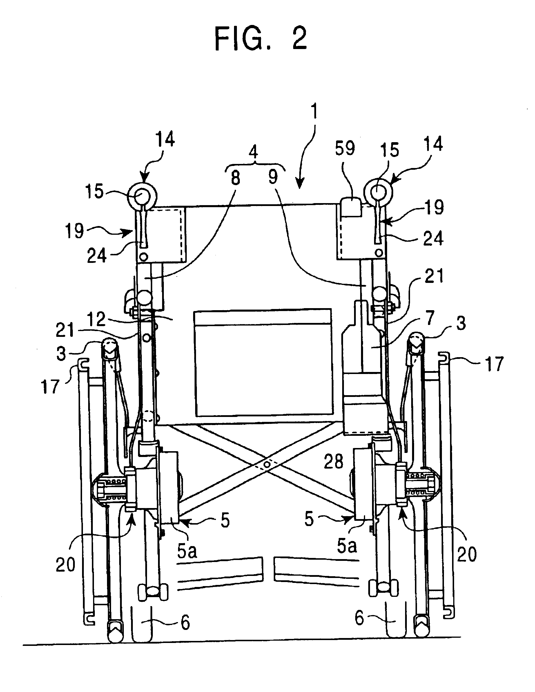
FIGS. 1 and 2 are a side view and back view of an electric-powered wheelchair 1 as an example of an electric-powered vehicle. The electric-powered wheelchair 1 has a wheelchair body 2 and right and left wheels (driving wheels) 3 provided on the right and left sides of the wheelchair body 2. The wheelchair body 2 includes wheelchair frames 4 and a pair of right and left electric-powered drivers 5 which each include a motor and a speed-reducing mechanism in a housing 5a.

The right and left wheels 3 as the driving wheels are attached to the electric-powered drivers 5. The wheels 3 are rotated by driving forces generated by the electric-powered drivers 5, and the driving forces are used as part of propulsion for the electric-powered wheelchair 1. Each driving force is called the “assisting driving force”. The wheelchair body 2 has, in its front part, a pair of right and left ca...


PUM


Abstract

An electric-powered vehicle includes electric-powered drivers for driving wheels, a controller for controlling the electric-powered drivers to generate an assisting driving force in accordance with a vehicle operating force by an operator, and a brake-operation unit for applying braking forces on the wheels. The vehicle also includes a brake-operation detector for detecting a brake operation performed by the brake-operation unit. When the brake-operation detector detects the brake operation, the controller controls the drivers to reduce the assisting driving force. This structure solves a problem caused by simultaneous generation of the braking forces and the assisting driving force.

Description

BACKGROUND OF THE INVENTION1. Field of the InventionThe present invention relates to an electric-powered vehicle such as an electric-powered wheelchair.2. Description of the Related ArtElectric-powered wheelchairs of the related art include a type of wheelchair in which a motor generates an assisting driving force in accordance with an operating force generated when a caregiver pushes or pulls the wheelchair body while holding operation handles. The operating force generated by pushing or pulling the wheelchair body is detected by using a sensor to detect a force applied on the operation handles.The wheelchair in which the assisting driving force is generated can be moved by the resultant of the operating force generated when the caregiver pushes or pulls the wheelchair body and the assisting driving force. This can reduce the load on the caregiver.In the vicinity of the operation handles, brake levers are provided. The brake levers are connected to wheel brake mechanisms by control...

Claims


Application Information

Patent Timeline
IPC IPC(8): A61G5/04A61G5/00B60L15/20
CPCA61G5/045A61G5/1018B60L15/2009A61G2005/048A61G2005/1054Y02T10/7275Y10S180/907A61G5/1037A61G5/048A61G5/1054Y02T10/64Y02T10/72
Inventor INOUE, TAKAHITOTAKEZAWA, YOSHINORI
Owner NABCO LTD
Learn More