
Control of oxygen storage in a catalytic converter

a technology of catalytic converter and oxygen storage, which is applied in the direction of electrical control, process and machine control, instruments, etc., can solve the problems of providing erroneous signals regarding the engine air fuel mixture, presenting its own problems, and a relatively long time delay for exhaust gas, so as to achieve maximum conversion efficiency

Inactive Publication Date: 2005-01-11
FORD GLOBAL TECH LLC
View PDF23 Cites 13 Cited by
  • Summary
  • Abstract
  • Description
  • Claims
  • Application Information

AI Technical Summary

Benefits of technology

The present invention provides a method and system for controlling an engine to maximize the conversion efficiencies of an emission control device for both HC and CO emissions, as well as NOx emissions. The method and system use an electronic control unit to obtain an adjusted feedgas air fuel ratio and an estimate of oxygen storage level in the emission control device. This allows for a more accurate closed-loop feedback control system for the engine and ensures more accurate estimation of the oxygen storage level by evaluating the estimate in view of the engine operating conditions. The technical effects of this invention include improved accuracy of the air fuel ratio measurement and the oxygen storage level estimate, as well as more accurate control of the engine to achieve desired emissions levels.

Problems solved by technology

This oxygen sensor, however, can provide erroneous signals regarding the engine air fuel mixture because of non-equilibrium effects in the exhaust gas.
Use of the secondary oxygen sensor, however, presents its own problems.
First, there is a relatively long time delay for the exhaust gas to travel from the engine to the secondary oxygen sensor.
In closed loop control systems, these characteristics can result in limit cycles in the commanded air fuel signals for the engine and, consequently, engine torque.
These conventional control systems, however, have several problems.
As discussed above, this signal is corrupted by a bias error that reduces the accuracy of the control system.
Second, the models fail to account for variations in the observability of the oxygen storage level in the emission control device.

Method used


Image

  • Control of oxygen storage in a catalytic converter
  • Control of oxygen storage in a catalytic converter
  • Control of oxygen storage in a catalytic converter

Examples


Embodiment Construction

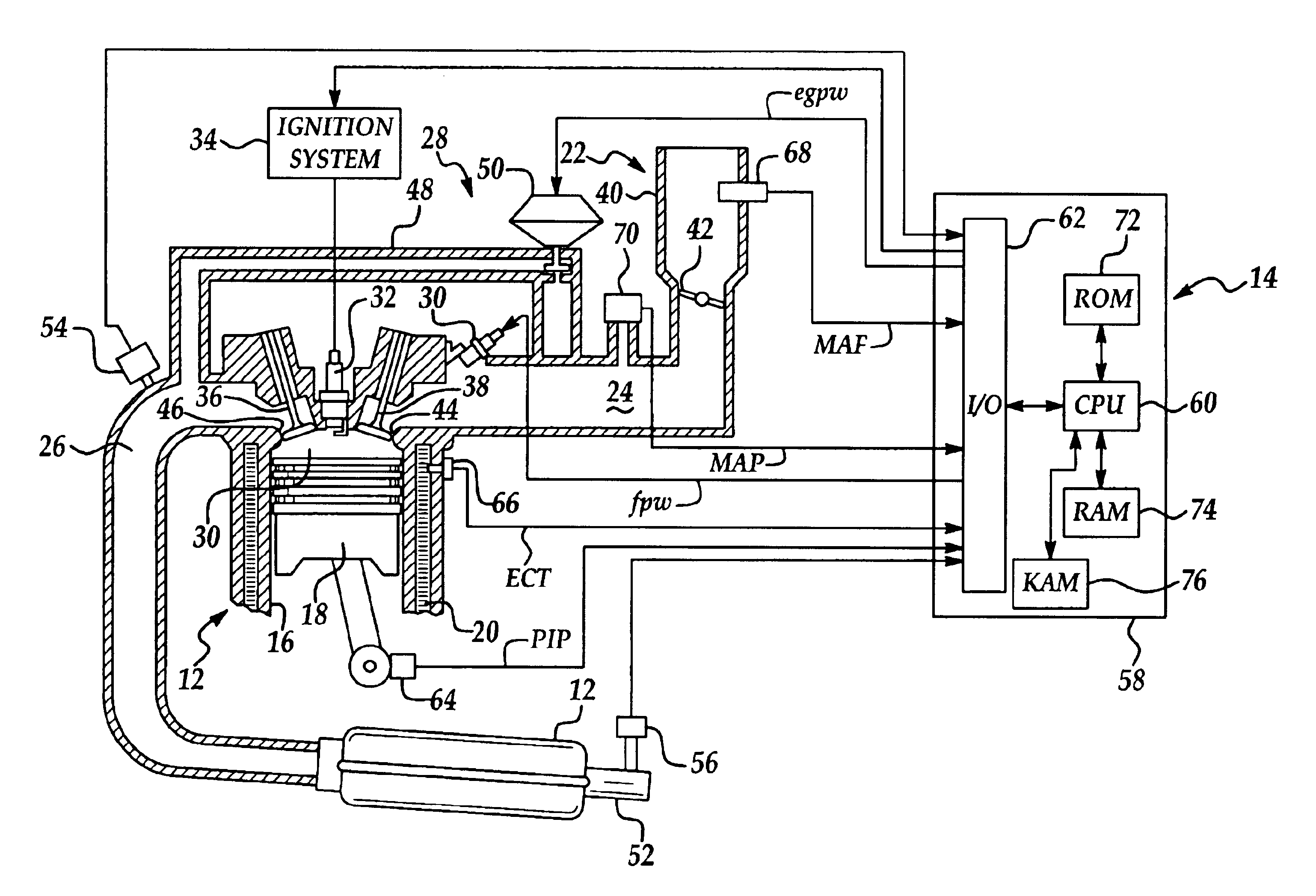
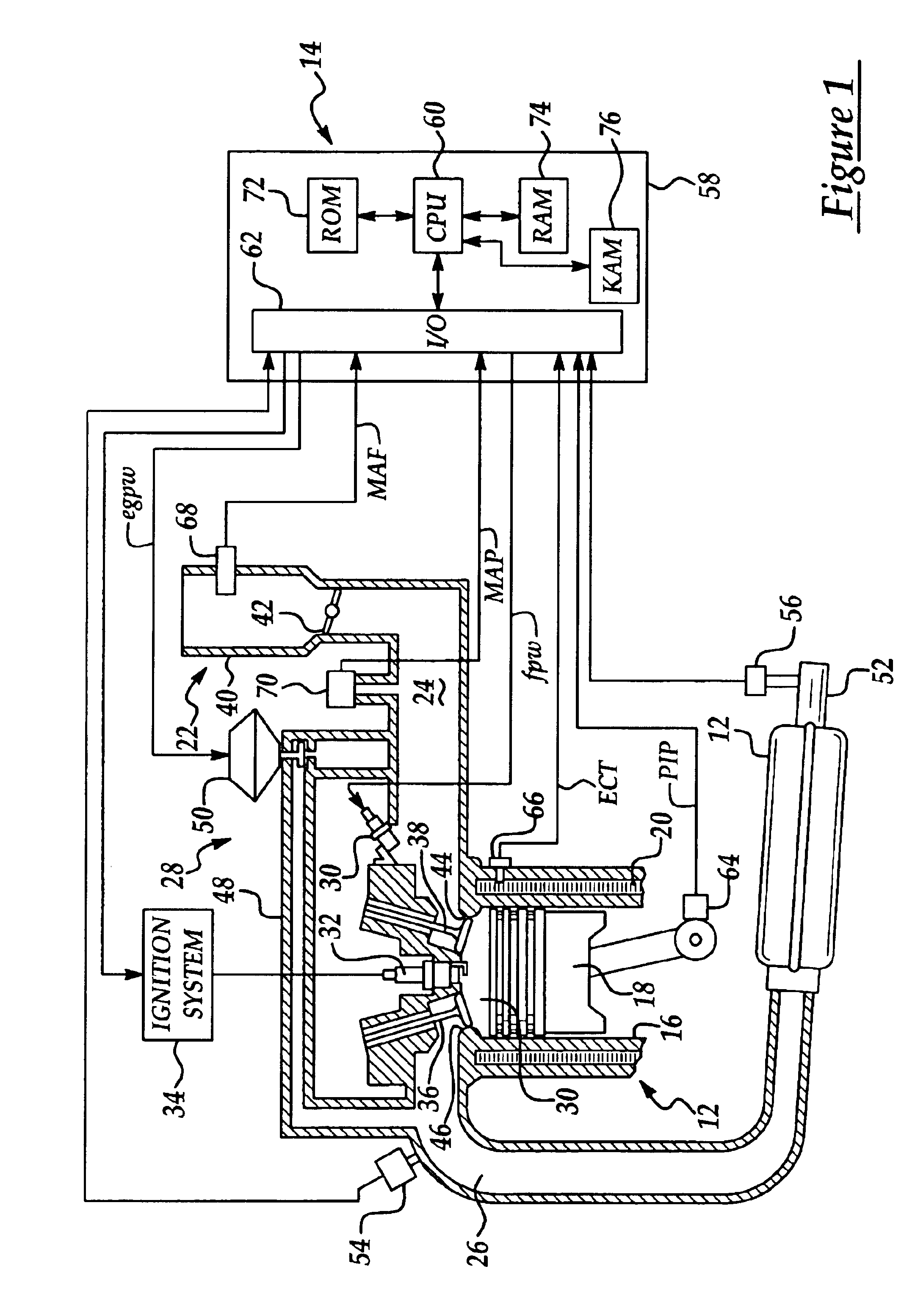
Referring now to the drawings wherein like reference numerals are used to identify identical components in the various views, FIG. 1 illustrates an internal combustion engine 10, an emission control device 12, and a system 14 in accordance with the present invention for controlling engine 10 in order to maintain an optimal oxygen storage level in device 12. By maintaining an optimal oxygen storage level in device 12, maximum engine robustness and minimum emissions are obtained.

Engine 10 is designed for use in a motor vehicle. It should be understood, however, that engine 10 may be used in a wide variety of applications. Engine 10 provides motive energy to a motor vehicle or other device and is conventional in the art. Engine 10 may define a plurality of combustion chambers or cylinders 16 and may also include a plurality of pistons 18, coolant passages 20, a throttle assembly 22, an intake manifold 24, an exhaust manifold 26, and engine gas recirculation (EGR) system 28, fuel inject...


PUM


Abstract

A system and method for controlling an engine to regulate the oxygen storage level in an emission control device are provided. The system includes oxygen sensors disposed in an exhaust gas stream of the engine upstream and downstream of the emission control device. The oxygen sensors generate a feedgas and tailpipe air fuel signals. The system includes an electronic control unit (ECU) configured to obtain an adjusted feedgas air fuel ratio responsive to the feedgas and tailpipe air fuel signals to correct bias in the feedgas air fuel signal. The (ECU) is further configured to obtain an estimate of an oxygen storage level in the emission control device responsive to the adjusted feedgas air fuel ratio and the tailpipe air fuel signal. Finally, the (ECU) is configured to generate a control signal for the engine responsive to the adjusted feedgas air fuel ratio and the oxygen storage level estimate.

Description

BACKGROUND OF THE INVENTION1. Field of the InventionThis invention relates to engine control systems and, in particular, to a method and system for controlling an engine to maintain optimal oxygen storage levels in an emission control device.2. Discussion of Related ArtConventional vehicles typically employ an emission control device such as a three-way catalytic converter to control emissions resulting from the combustion process in an internal combustion engine. When a rich air fuel mixture is present during the combustion process, the emission control device oxidizes hydrocarbon (HC) and carbon monoxide (CO) emissions. When a lean air fuel mixture is present during the combustion process, the emission control device takes up oxygen from the exhaust gas to reduce nitrous oxide (NOx) emissions.The emission control device is designed to store a finite amount of oxygen. If the maximum oxygen storage capacity of the device is attained during a lean transient of the engine a NOx breakt...

Claims


Application Information

Patent Timeline
Patent Type & Authority Patents(United States)
IPC IPC(8): F01N11/00F02D41/02F02D41/14F01N7/04F01N7/00F01N7/02F02M25/07F01N13/02F01N13/04
CPCF01N3/101F01N11/007F02D41/0295F02D41/1441F01N13/011F01N13/0093F01N13/009F01N2550/02F02D41/1443F02M25/0715Y02T10/47Y02T10/22F02D2200/0814F02M26/13Y02T10/12Y02T10/40
Inventor FIENGO, GIOVANNICOOK, JEFFREY ARTHURGRIZZLE, JESSY W.
Owner FORD GLOBAL TECH LLC
Learn More