
Hydraulic and electric umbilical connection for an inspection vehicle for inspecting a liquid-filled tank

a technology for liquid-filled tanks and hydraulic hoses, which is applied in the direction of insulated conductors, cables, instruments, etc., can solve the problems of unintentional inspection, low safety of hydraulic hoses formed from rubber or nylon reinforced thermoplastics, and adverse effects on air quality. , to achieve the effect of discharging dynamic and static charges

Inactive Publication Date: 2005-01-04
A HAK INDAL SERVICES
View PDF25 Cites 9 Cited by
  • Summary
  • Abstract
  • Description
  • Claims
  • Application Information

AI Technical Summary

Benefits of technology

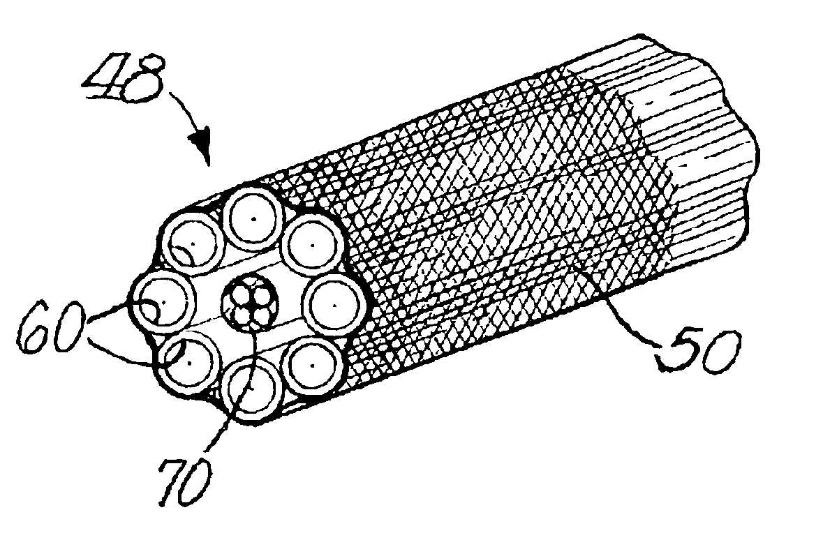
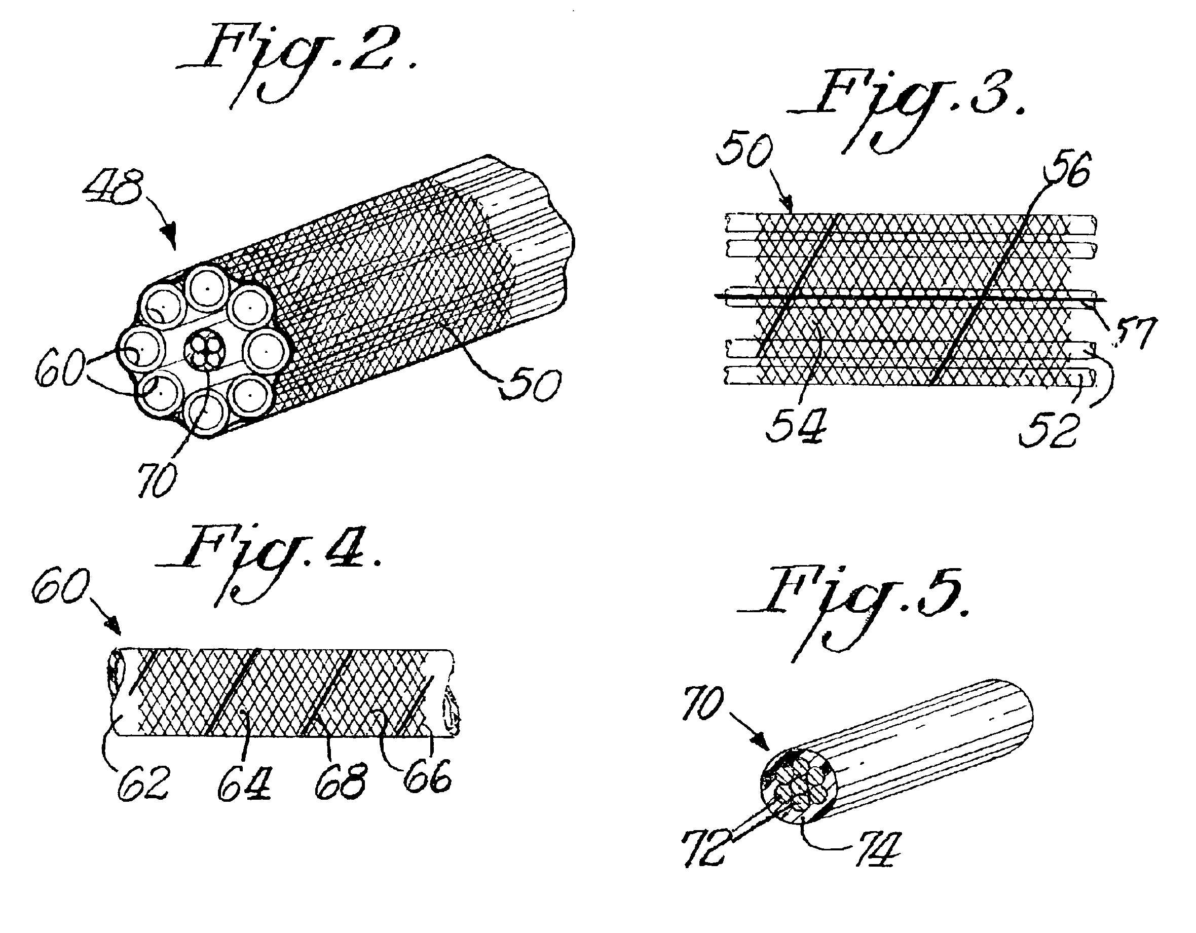
The outer sheath of the umbilical connection may be formed as a triaxial or multi-axial braid in which the first plurality of polymeric strands form a bias weaving together with the one or more electrically conductive strands, and the second plurality of polymeric strands extends axially, such that when the sheath is installed around the hoses the second plurality of polymeric strands extends along such length. In such a preferred construction, the first plurality of polymeric strands are formed from nylon-coated polymeric fiber, the second plurality of polymeric strands are liquid crystal polymer fibers and the electrically conductive strand(s) are copper. The braid angle preferably is in the range of 45 to 80 degrees, and gaps preferably are left between the strands in the braid. With such braid with gaps, liquids that contact the umbilical connection will more rapidly drain away from the umbilical connection when the umbilical connection emerges from a liquid containing tank or other liquid environment.

Problems solved by technology

Air quality may be impacted adversely if hydrocarbon vapor emissions exceed permitted amounts.
Because of the hazards associated with confined space entry within the vapor space, particularly in flammable atmospheres, entry for inspection purposes is rarely permitted.
Known hydraulic hoses formed from rubber or nylon reinforced thermoplastics are not “intrinsically safe” because excessive heat energy builds from friction as the hose surface contacts the pulley or the surfaces of the internal floating roof tank when the inspection vehicle is deployed into the tank.
In addition, rubber materials may degrade in caustic chemical environments.
Known PTFE hydraulic hoses can withstand caustic environments, but have not been found conductive enough to dissipate static charges.
When such PTFE hoses are covered with a metallic braided outer sheath, such as stainless steel, to increase conductivity, they have also been found unsafe because the braided sheath scrapes or punctures the coatings over electrical cables bundled together with the hydraulic hoses in an umbilical connection.
Moreover, the stainless braid can also scrape the surfaces of the internal floating roof, generating a spark or building up heat toward possible ignition in the vapor space.
Prior sheathing materials have not satisfied these rigorous requirements.

Method used


Image

  • Hydraulic and electric umbilical connection for an inspection vehicle for inspecting a liquid-filled tank
  • Hydraulic and electric umbilical connection for an inspection vehicle for inspecting a liquid-filled tank
  • Hydraulic and electric umbilical connection for an inspection vehicle for inspecting a liquid-filled tank

Examples


example

The Table below sets out a strand composition for a triaxial overbraid sheath for an umbilical connection.

BiasAxialNylon coatedBiasHot meltAxialAxialVECTRAN ®0.008″ copperadhesive0.008″ copperKEVLAR ®Diameter2.752.752.752.752.75Angle62.062.0000Raw yd / lb11001754239017543144Carrier764404040Ends per carrier11211Fiber density0.052 lb / in30.322 lb / in30.041 lb / in30.322 lb / in30.052 lb / in3Part fiber50%50%50%50%50%volumeOne layer0.01820.00010.00580.00010.0016thicknessPercent coverage59.7%1.2%20.3%10.4%oz / yd29.80.32.50.8FT / LB20.42618.689.6131.6235.8PPI8.70.40.00.00.0EPI9.8Yarn centerline0.102spacingGap size0.0625

As reported in the Table above, the “Diameter” is the nominal outer diameter of the finished braid. The “Angle” represents the angle of the bias yarns in relation to the axial yarns. The angle is reported in degrees. The “Carrier” concerns the total number of yarns of a particular type running in the same direction. “Ends per carrier” concerns the number of yarn bobbins per carrier. “F...


PUM


Abstract

An umbilical connection for use in a hazardous environment like a floating roof storage tank has one or more hydraulic hoses, one or more electrical cables or a combination thereof. Each hydraulic hose has a static dissipative and abrasion resistant covering. Each electrical cable has an abrasion resistant coating. The hoses and cables are bundled and wrapped in a static dissipative and abrasion resistant open mesh sheath or an overbraid to form the umbilical connection.

Description

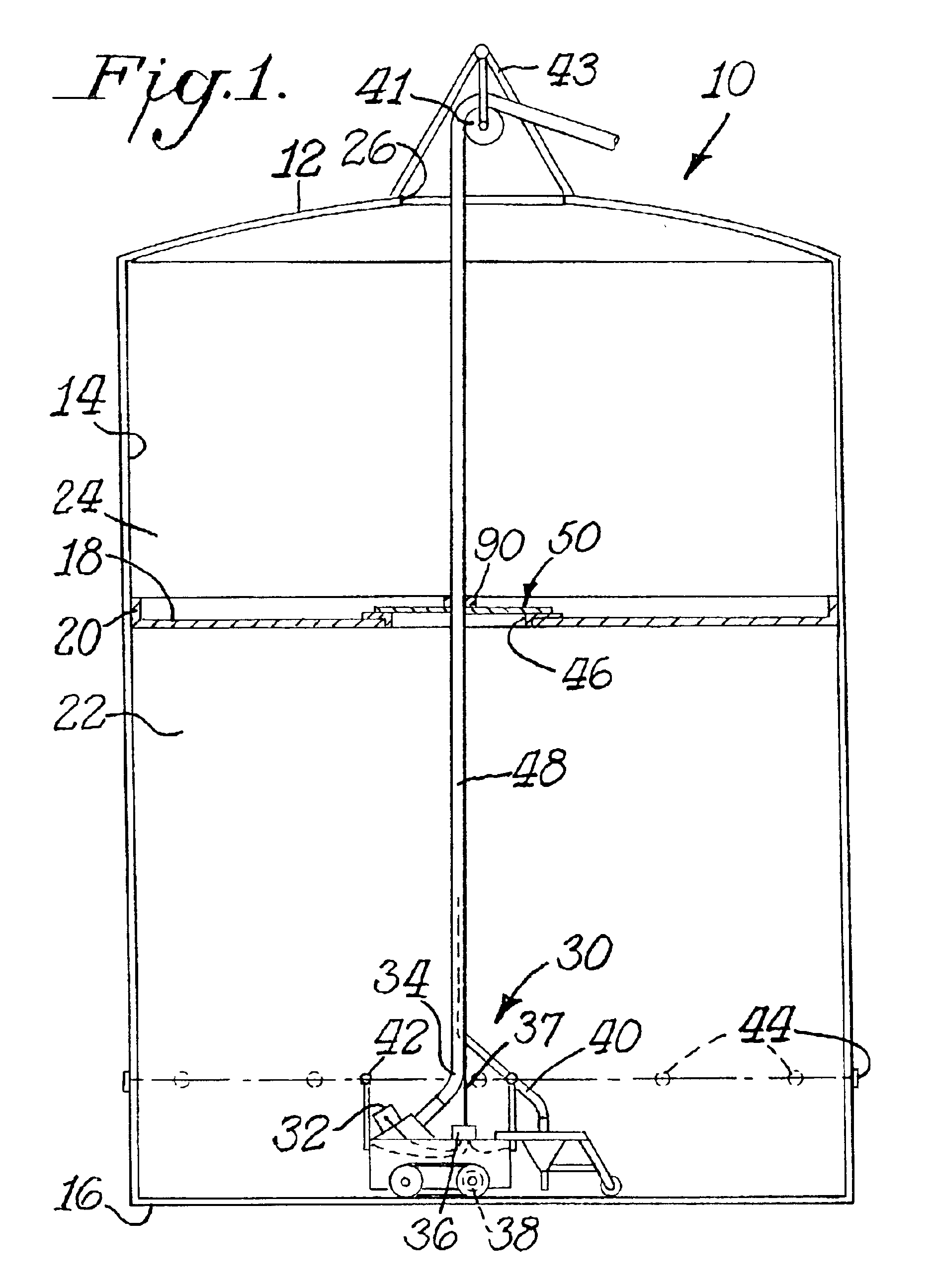
This invention relates to an umbilical connection that includes one or more hydraulic lines and one or more electric lines or wire harnesses linking a robotic inspection vehicle deployed in a liquid-filled tank to a control station located outside such tank. The hydraulic and electric lines and the umbilical connection formed from a plurality of such lines have static dissipative sheathing to prevent spark generation that could lead to explosions when the inspection vehicle is deployed in flammable or other hazardous environments, such as the vapor space above a floating roof in a floating roof storage tank for gasoline or other hydrocarbon fuels.BACKGROUND OF THE INVENTIONA floating roof storage tank generally has a solid cylindrical outer wall covered by a solid sloped or dome-shaped roof. A floating roof is held within the volume defined by the outer wall and roof. The floating roof extends over the liquid contents held within the volume, and forms a vapor seal around the interna...

Claims


Application Information

Patent Timeline
IPC IPC(8): D04C1/02D04C1/00F16L11/22F16L11/00G01M99/00
CPCF16L11/22D04C1/02D07B1/147D07B2201/209
Inventor SILVERMAN, EUGENE B.GILBERT, DAVID L.SKALLOS, RICHARDLAUTENSCHLAGER, JOEL L.
Owner A HAK INDAL SERVICES
Learn More