
Analyte detection system

a detection system and analyte technology, applied in the field of detection systems, can solve the problems of disadvantaged prior systems employing multiple fluorescent labels, affecting the detection and quantification of analyte in these systems, and difficult to measure the absorption of particles, etc., and achieve the effect of time efficien

Inactive Publication Date: 2005-01-04
BECKMAN COULTER INC
View PDF50 Cites 44 Cited by
  • Summary
  • Abstract
  • Description
  • Claims
  • Application Information

AI Technical Summary

Benefits of technology

An advantage of the invention is that multiple analytes may be detected simultaneously in an automated system. For example, a panel of particles may be prepared, composed of multiple subpopulations of particles, where each individual subpopulation of particles is specific to a different analyte of interest. The panel of particles is allowed to react with a test sample and then passed through the detection system. In this manner, a panel of analytes may be simultaneously detected and quantified. Thus, the invention is time efficient in that multiple assays may be completed in one reaction. Examples of panels known to those skilled in the art that may be used with the invention include electrolyte panels, hormone panels, and such. It is understood that other multi-analyte panels are known to those with skill in the art, and can be employed in the detection system of the present invention, with reference to this disclosure.

Problems solved by technology

A disadvantage of employing size or color as a distinguishing markers is that these systems permit the labeling of only a few distinct subpopulations of particles.
A disadvantage of absorbance markers is that absorbance in a particle is difficult to measure and is not a particularly sensitive method of detection.
However, there are several distinct disadvantages to prior systems.
Prior systems employing multiple fluorescent labels can be disadvantaged when separate space is not reserved for the emission spectra for the analyte of interest.
Overlapping emission spectra between an analyte and a fluorochrome can hinder detection and quantification of the analyte in these systems.
These extraneous sources of fluorescence interfere with particle detection and with accurate detection and quantification of analytes by fluorescent labeling.
Indistinct emission spectra make accurate identification and quantification between multiple subpopulations of particles difficult.
Interaction between multiple fluorescent labels limits the number of distinguishable particle species and interaction between the fluorescent labels and fluorescent analytical dyes limits the quantitative detection capabilities of the device.
Complex signal processing devices must be employed to compensate for the indistinct spectra, adding to the cost of the detection system.
Prior analytical detection systems employing particle technology suffer from one or more of the following disadvantages: 1) limited accuracy, 2) limited sensitivity; 3) inadequate numbers of labels for the multitude of analytes to be detected; 4) expensive equipment; and 5) time consuming multiple reaction steps.

Method used


Image

  • Analyte detection system
  • Analyte detection system
  • Analyte detection system

Examples


example1

Cyanine Compounds Employed as Fluorescent Labels

IR-792 perchlorate, as shown below in Structure D, is a commercially available fluorescent label, useful in the present invention. IR-792 perchlorate, commercially available from Aldrich Chemical Company, is a fluorescent ring-locked cyanine compound that is excited by a 782 nm diode laser with a fluorescence emission frequency of 821 nm. The compound has good solubility in methylene chloride and stability in methylene chloride over time. FIG. 4, an overlay of the emission spectra of IR-792 perchlorate in methylene chloride for a two-month period, shows the stability of IR-792 perchlorate in solvent over time.

Structure D. IR 792 Perchlorate.

As an example of a pair of fluorescent labels used for particle coding, IR 792 perchlorate is incorporated in combination with Compound 6 according to the present invention. Compound 6 is excited by a 782 nm diode laser and has a fluorescence emission of 863 mm. Compound 6 has good solubility and s...

example 2

Ring-Locked Dibenzocyanine Compounds Used as Fluorescent Label Pairs

In another example, fluorescent Compounds 5a and 5b and Compounds 5c and 5d are employed in combination as fluorescent labels for coding particles. Compounds 5a-d are ring-locked dibenzocyanine compounds with a pair of extended alkane side chains. The label pairs differ by the inclusion or absence of a chlorine atom attached to the cyanine backbone above the locking ring. The alkane side chains increase the solubility of the charged labels in particle solvents and polymers and the stability of the labeled particles. Inclusion of the chlorine atom in the cyanine backbone causes the molecule to both absorb and emit at longer wavelengths than molecules that lack the chlorine atom. Table 3 summarizes the spectral data for Compounds 5a-d.

TABLE 3Summary of Spectral Data for Compounds 5a-d.λmaxEm.Compound(methylene chloride)(methylene chloride)5a787 nm833 nm(Ex. 782 nm)5b820 nm860 nm(Ex. 782 nm)5c787 nm833 nm(Ex. 782 nm)5d...

example 3

Preparation of Compound 6, [2-[2-[2-Phenylsulfyl-3-[(1,3-dihydro-3,3-dihydro-3,3-dimethyl-1-propl-2H-benzoindol-2-ylidene)ethylidene]-1-cyclohen-1-yl]ethenyl]3,3-dimethyl-1-propylbenzoindolium] Iodide

Preparation of N-propyl-1,1,2-trimethyl-1H-benzyl indole iodide (2, R═(CH3)2CH3). To a one-neck round bottom flask, equipped with stir bar, was charged with 1,1,2-trimethyl-H-benzyl-indole (2 g, 9.6 mmole, 1) and iodopropane (2.4 g, 14.3 mmole). The flask was placed in an oil bath (pre-heated at 90 EC) for 24 hrs under N2. The resulting reaction mixture was allowed to cool to ambient temperature and filtered. The solid was washed with iodopropane (5 mL), hexane (50 mL), and dried under vacuum at 60° C. for 6 hrs gave 3.2 g of a red colored solid in 88% yield. 1H NMR (CDCl3) δ ppm: 1.15 (t, 3H), 1.88 (s, 6H), 2.08 (m, 2H), 3.21 (s, 3H), 4.79 (t, 2H), 7.67-7.74 (m, 2H), 7.82 (d, 1H), 8.04-8.13 (m, 3H). 13C NMR (CDCl3) δ ppm: 11.29, 16.82, 21.62, 22.69, 51.44, 55.83, 112.54, 122.76, 127.55...


PUM

PropertyMeasurementUnit
maximum wavelengthsaaaaaaaaaa
excitation wavelengthsaaaaaaaaaa

Abstract

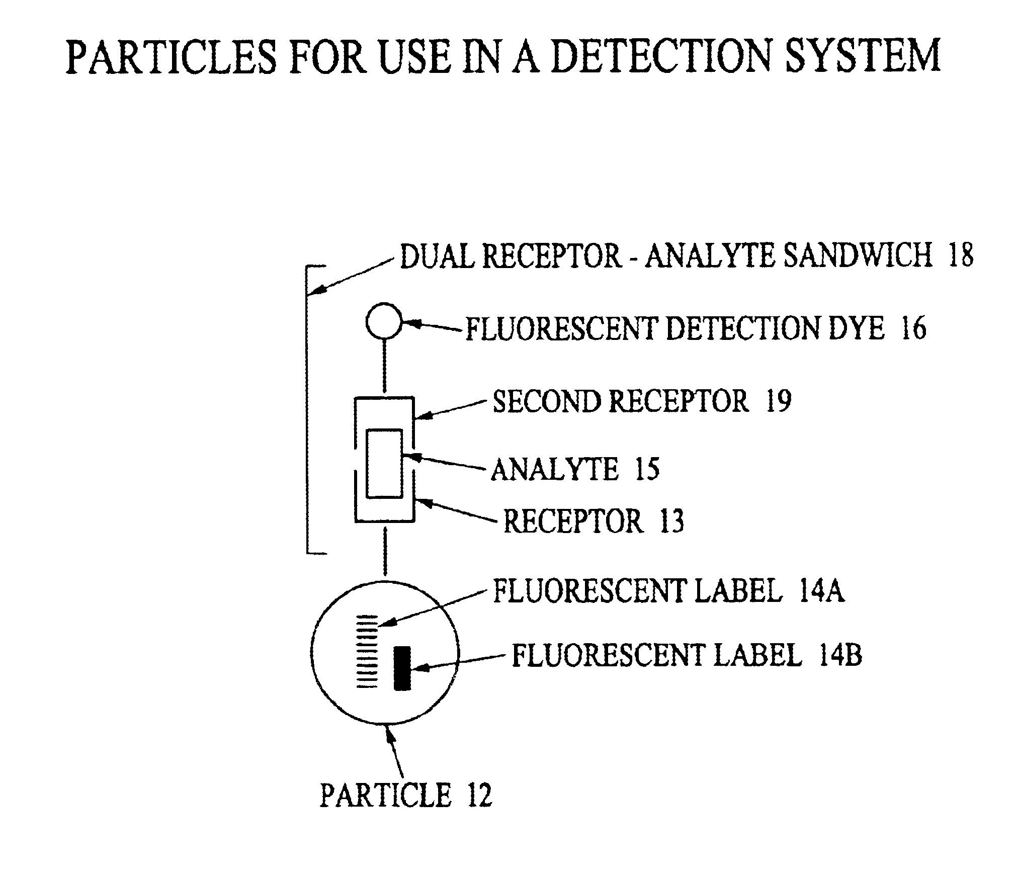
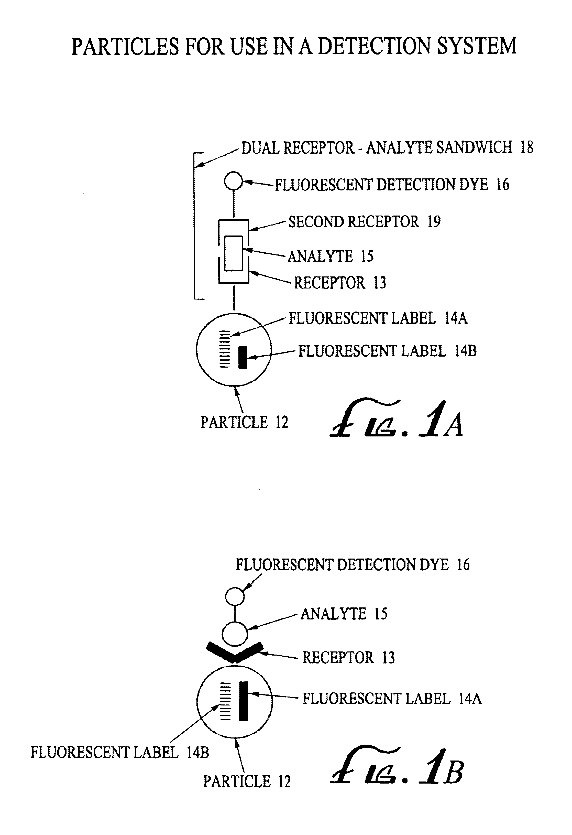
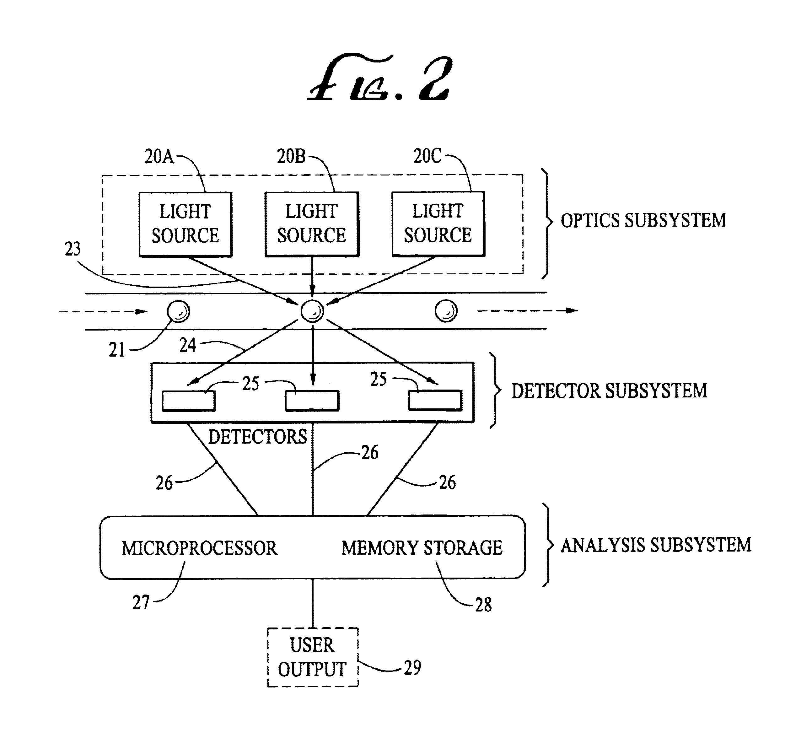
An analyte detection system utilizing a combination of fluorescent labels for labeling particles and an analyte specific fluorescent analyte detection dye. The particles contain a combination of fluorescent labels for coding the particles and an analyte specific fluorescent dye. The particles can be used to identify and quantify analytes in an analytical sample by reaction of the analytical sample with the particles. An analytical device can identify the particles according to the combination of fluorescent labels. The device can then correlate the identified particle with the analyte specific fluorescent analyte detection dye. Multiple subpopulations of particles can be used to identify and quantify multi-analytes in a single analytical sample. Near infrared (NIR) fluorescent labels useful in the detection system are also provided.

Description

BACKGROUNDThe present invention relates to a detection system and method for measuring fluorescently labeled analytes by their interactions with particles encoded with fluorescent labels, and further relates to fluorescent label compositions for coding polymeric microbeads or particles.Polymeric beads are useful analytical tools for detecting and measuring various analytes especially when combined with flow cytometry systems and methods. The term polymeric beads is referred to in the art and used hereinafter interchangeably as beads, particles, microbeads, microparticles, and microspheres. Analytes of interest are often bound to a particle and identified by a corresponding characteristic of the particle such as size, magnetism, and spectroscopic properties including absorbance, light scatter, color, and fluorescence at one or more wavelengths.For example, prior art patents describe the use of particle size or color as parameters for distinguishing between subpopulations of particles...

Claims


Application Information

Patent Timeline
Patent Type & Authority Patents(United States)
IPC IPC(8): G01N33/542G01N33/58G01N33/536G01N15/14C09B23/00C09K11/06G01N21/78G01N33/543
CPCG01N33/542G01N33/587G01N33/582G01N15/1459Y10T436/13G01N2015/1438
Inventor BELL, MICHAEL L.LIN, YUANMICHAEL, JOSEPHINE M.PENTONEY, JR., STEPHEN L.TSAY, TSONG-TSEH
Owner BECKMAN COULTER INC
Learn More