Device for storage and conveyance of bulky holders

Inactive Publication Date: 2005-01-04
FOUNTAIN PATENTS I O
View PDF7 Cites 3 Cited by
  • Summary
  • Abstract
  • Description
  • Claims
  • Application Information

AI Technical Summary

Benefits of technology

The object of the present invention is to reduce the abovementioned problems, in particular to limit the number of drives and in doing so to keep the construction relatively simple, while the possibility of automation and also efficient utilization of space are retained.
The operation of the device is relatively simple. A tier with 2*N positions for holders and 2*N-1 carriers is filled with holders, in principle one on each carrier. However, the carriers may be arranged in such a way that several holders with smaller dimensions fit on them. When a certain holder has to be transported further from there, the circuit in question is put into operation, the carriers being allowed to circulate until the holder in question is situated at a discharge point of a longitudinal path, where said holder can be removed from the circuit. The holder is lifted off a carrier using suitable means, for example a forklift truck. A new holder can be placed on the empty carrier and stored in this way.
Since the carriers are positioned in a virtually horizontal position by means of the transverse tracks, before the carriers can be transferred from one longitudinal path by way of the transverse tracks to an adjoining longitudinal path, blocking means are advantageously provided in the longitudinal paths, in particular for the carriers in the penultimate positions, so that sufficient distance is present between the holders on the last (lowest) carrier and penultimate carrier to allow the horizontal positioning. Blocks which can be lowered in the surface are an example of such blocking means, which are actuated, for example, when sensors detect the presence of a carrier in the last position. Spacers between the carriers can produce the same effect, but lead to an overall lengthening and widening of the conveyance circuit with the same number of carriers.

Problems solved by technology

Such movements take a relatively large amount of time.
However, each movement usually has to be paid for, which incurs additional costs.
Furthermore, the space is being used inefficiently, since aisles are needed between the rows for the gantry cranes.
The same problem occurs in distribution centres, where pallets or other holders filled with goods are stored temporarily on racks comprising several levels.
A large amount of floor space is therefore needed.
A disadvantage of such a system is that separate drives, such as chain drives, are needed for each conveyor, as are separate intermediate parts, for example roller conveyors, for transferring a container from a longitudinal conveyor to a transverse conveyor.
Disadvantages of this known system are that drives are needed for moving the carriages, and that each carriage has to be provided with a double travelling mechanism.

Method used


Image

  • Device for storage and conveyance of bulky holders
  • Device for storage and conveyance of bulky holders
  • Device for storage and conveyance of bulky holders

Examples


Embodiment Construction

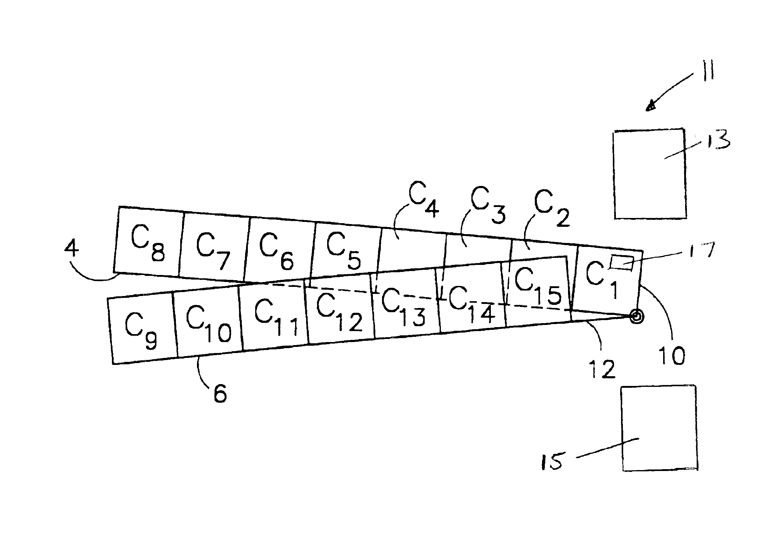
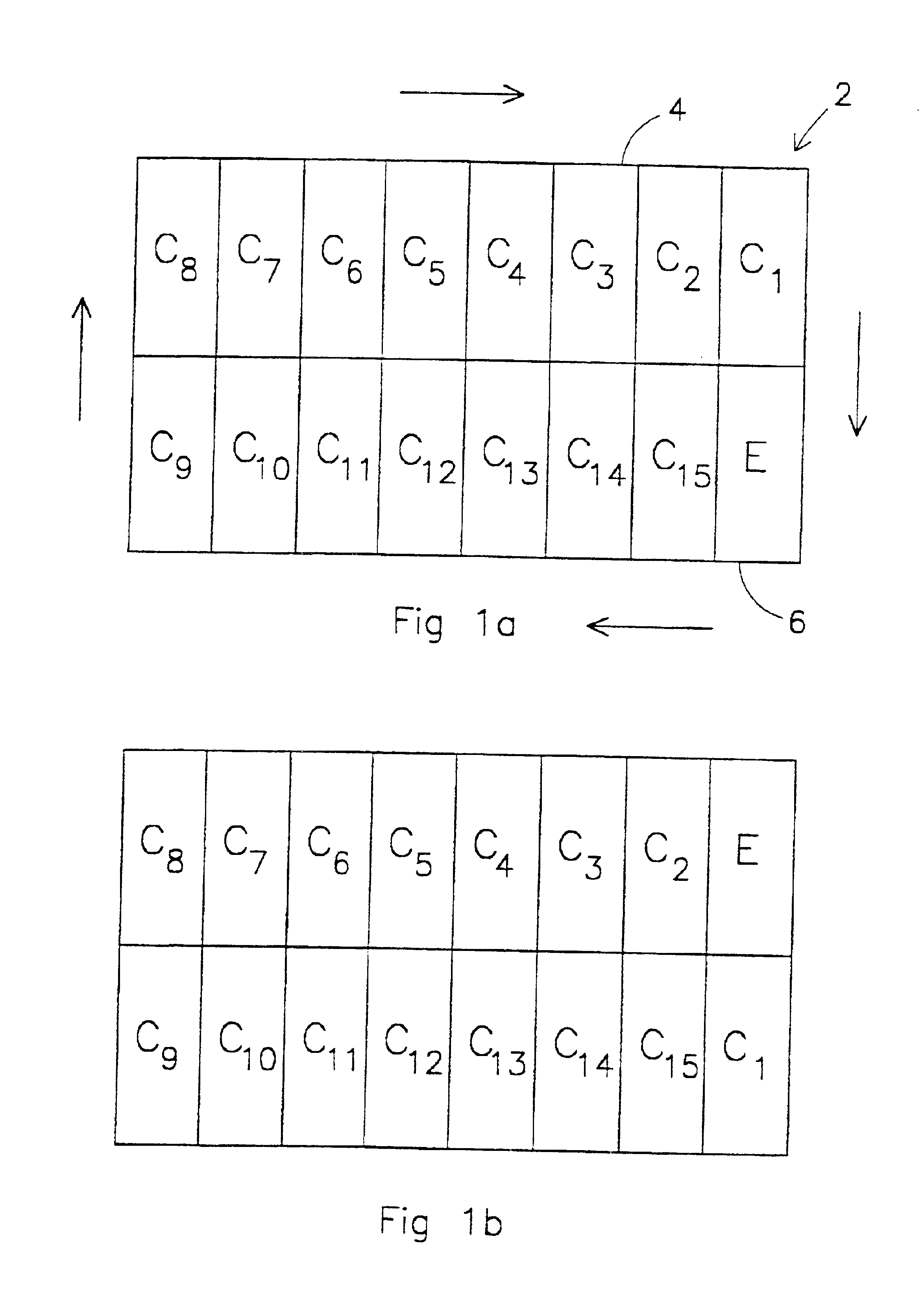
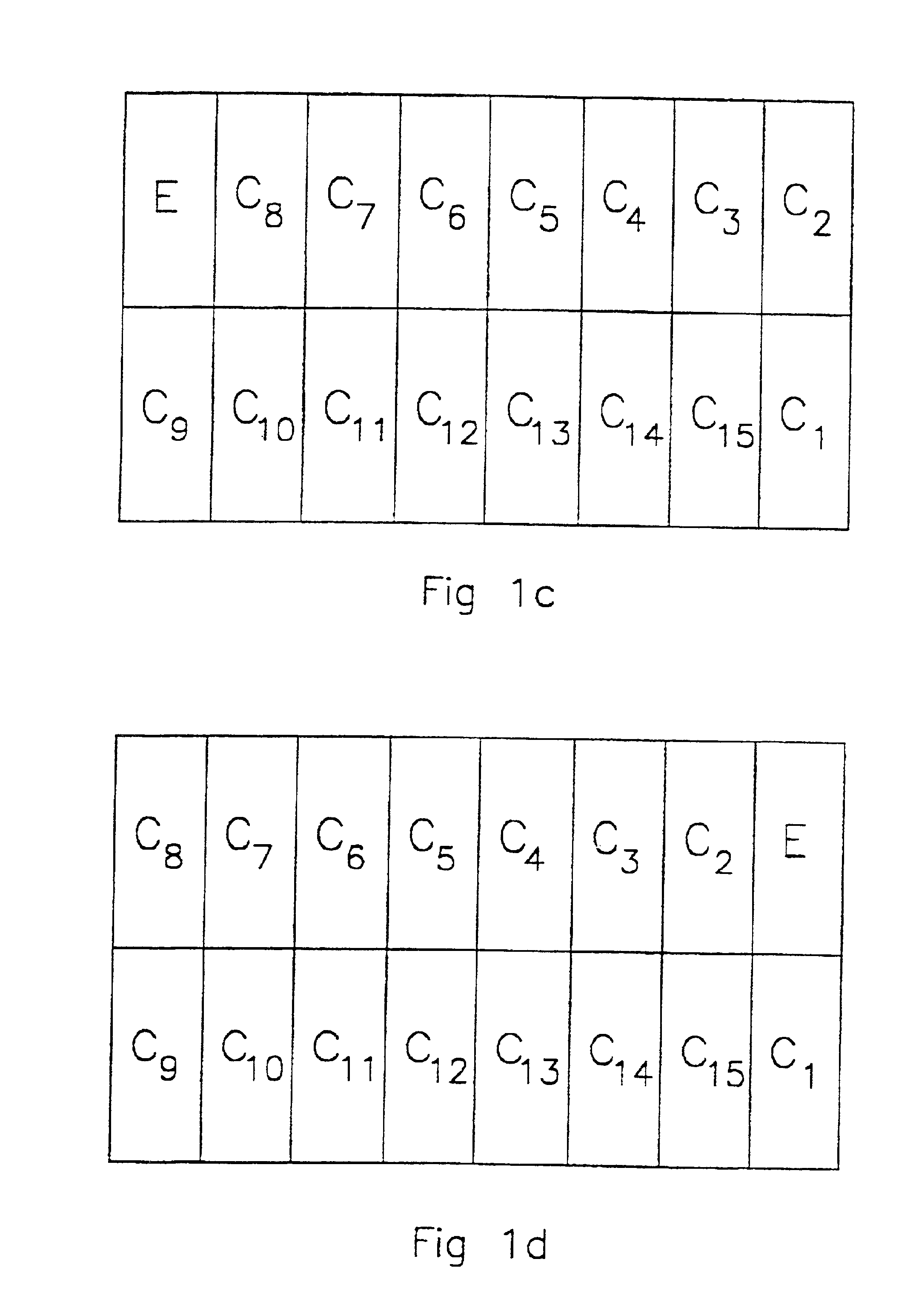
FIGS. 1a to 1e show diagrammatically in top view the circulation route of containers Cm, E representing an empty position. The direction of circulation is indicated by arrows. A conveyance circuit is indicated by reference numeral 2, said conveyance circuit consisting of a longitudinal path 4 and a longitudinal path 6, which is disposed parallel to and adjoining longitudinal path 4. See FIG. 2, which is a diagrammatic side view of the situation shown in FIG. 1a. The longitudinal paths 4 and 6 have opposite angles of inclination of approximately 0.2°, which is greatly exaggerated in this figure for the sake of clarity. For the sake of simplicity, transverse tracks are not shown in these FIGS. 1 and 2. In the situation shown, each longitudinal path has eight positions for carriers with containers. The longitudinal path 4 is filled with carriers with containers C1-C8, while the longitudinal path 6 comprises containers C9-C15 and also has an empty position E that corresponds to the top ...


PUM


Abstract

The invention relates to a device for storage and conveyance of bulky holders (C), comprising at least one tier (32), each tier comprising at least one conveyance circuit (2) for the holders (C), and each conveyance circuit (2) comprising at least two longitudinal paths (4, 6) disposed substantially parallel to each other, for conveyance of the holders (C) in the direction of the longitudinal paths (4, 6), which longitudinal paths (4, 6) each define a first predetermined number (N) of adjoining holder positions for the holders (C) while two adjacent longitudinal paths (4, 6) of a conveyance circuit (2) slope from the same end in opposite directions, and in which transverse tracks situated at the opposite ends of the longitudinal paths and movable at least in the vertical direction are also provided, for conveyance of the holders (C) in the direction of the transverse tracks, which transverse tracks can transfer the holders (C) to and from the longitudinal paths (4, 6), and also comprising a second predetermined number (M≦2*N−1) of carriers (14) which are movable along the longitudinal paths and transverse tracks and are designed to take one or more holders (C), lifting means (34) being provided for moving the transverse tracks in the vertical direction.

Description

BACKGROUND OF THE INVENTIONThe present invention relates to a device for storage and conveyance of bulky holders, in particular containers.Container terminals are generally known and are used for the temporary storage and subsequent distribution of containers, which are brought into a seaport in large numbers in, for example, container ships, and are then transported further by rail in goods trains, by road in lorries or on waterways in smaller vessels. In order to permit temporary storage of the large quantity of containers, said containers are stacked on top of one another in rows spaced apart in a storage yard, generally with the aid of mobile gantry cranes operated by crane drivers. The free space between the rows is necessary for the tracks along which the mobile cranes can move. When a particular container from such a stack has to be transported further, the containers stacked on top of this particular container first have to be moved to a free position before the particular c...

Claims


Application Information

Patent Timeline
IPC IPC(8): B65G1/08B65G1/06B65G63/00B65G63/02B65G1/12
CPCB65G1/06B65G63/025B65G1/08
Inventor HOOGLAND, HENDRICUS ANTONIUS
Owner FOUNTAIN PATENTS I O
Why Eureka
Try Eureka