Eureka AIR delivers breakthrough ideas for toughest innovation challenges, trusted by R&D personnel around the world.

Current sensing circuit and method of a high-speed driving stage

a technology of current sensing circuit and high-speed driving stage, which is applied in the direction of pulse manipulation, pulse technique, instruments, etc., can solve the problems of reducing efficiency, increasing power consumption, and complicating circuits

Inactive Publication Date: 2004-09-14
GLOBAL MIXED MODE TECH
View PDF6 Cites 39 Cited by
  • Summary
  • Abstract
  • Description
  • Claims
  • Application Information

AI Technical Summary

Benefits of technology

The present invention also allows the use of differential output mode, which, however, makes the circuit design more complicated and takes up more chip space. Furthermore, the transistors of the present invention can also be replaced with resistors that can function just as well with equivalent effects.

Problems solved by technology

1. The use of series resistance will increase power consumption and lower efficiency.
2. The use of an operational amplifier will complicate the circuits and slow down the operating speed.
3. The series resistance inside the integrated circuits will fluctuate due to process variation and create errors of detecting current.
However, the '636 patent requires a three-fold bias current due to the demand of its circuit design so that the power consumption of the '636 patent will increase.
Additionally, the '636 patent requires the use of differential output mode so as to determine the change of the loading current, so its circuit design is more complicated and takes up more chip space.
The present invention also allows the use of differential output mode, which, however, makes the circuit design more complicated and takes up more chip space.

Method used


Image

  • Current sensing circuit and method of a high-speed driving stage
  • Current sensing circuit and method of a high-speed driving stage
  • Current sensing circuit and method of a high-speed driving stage

Examples


Embodiment Construction

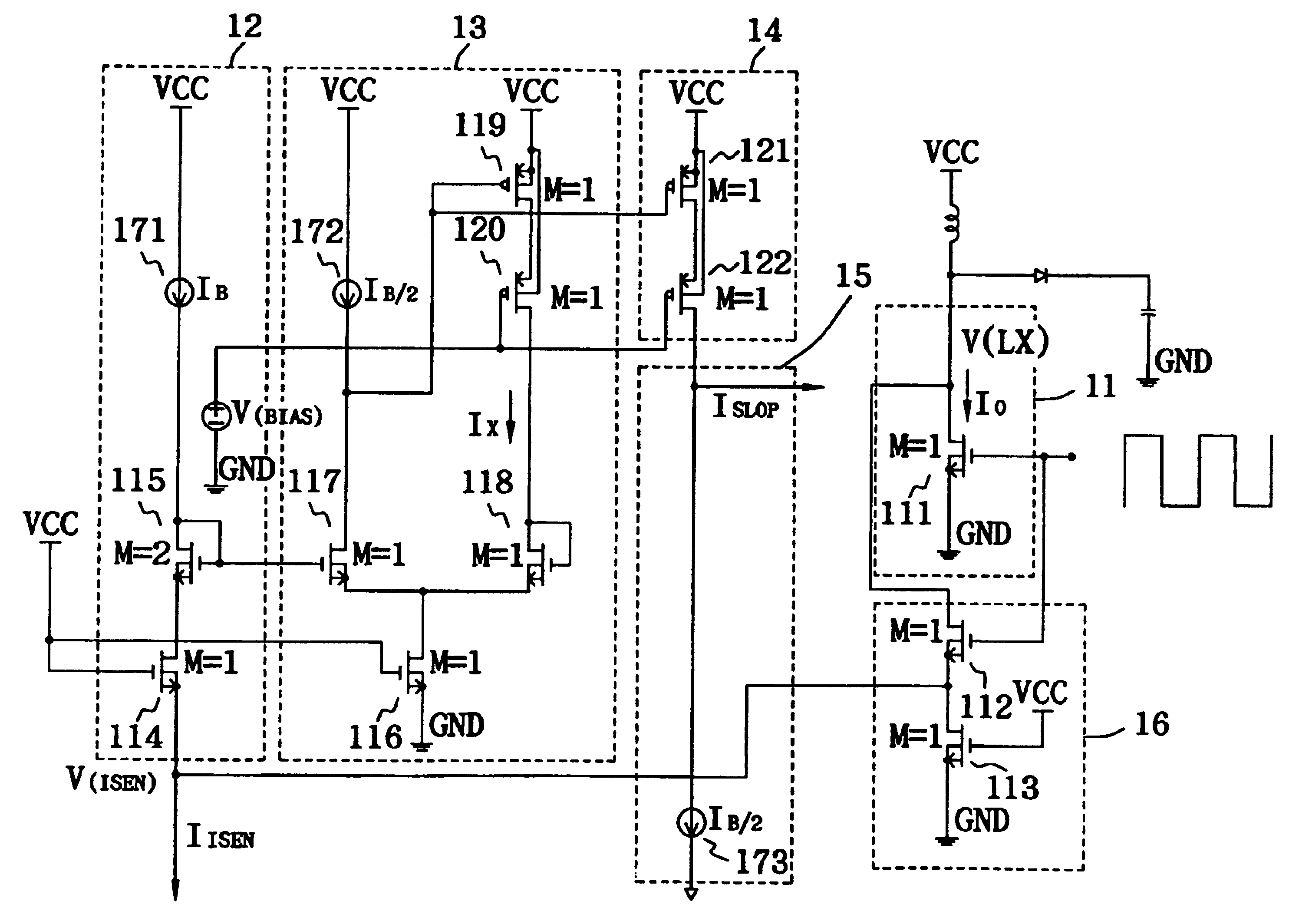
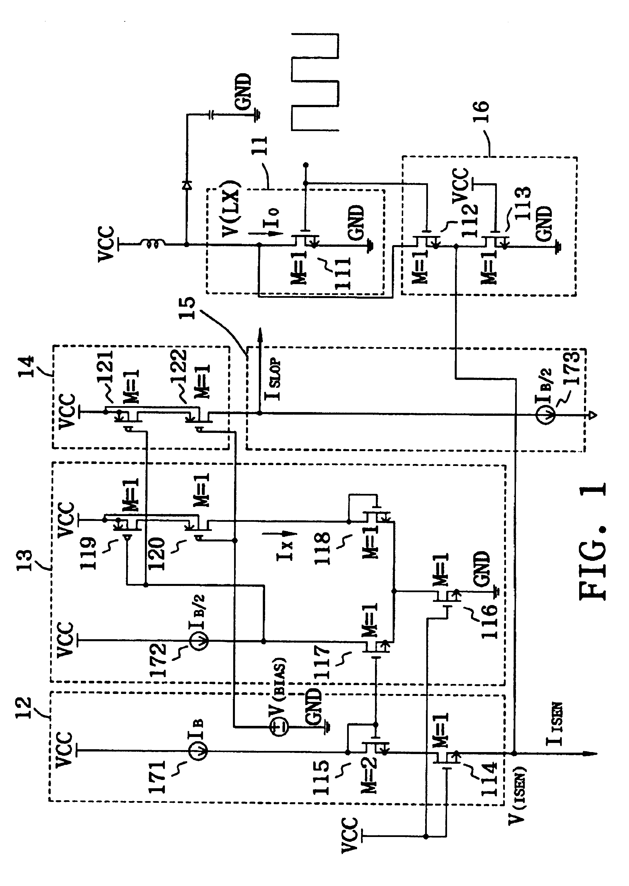
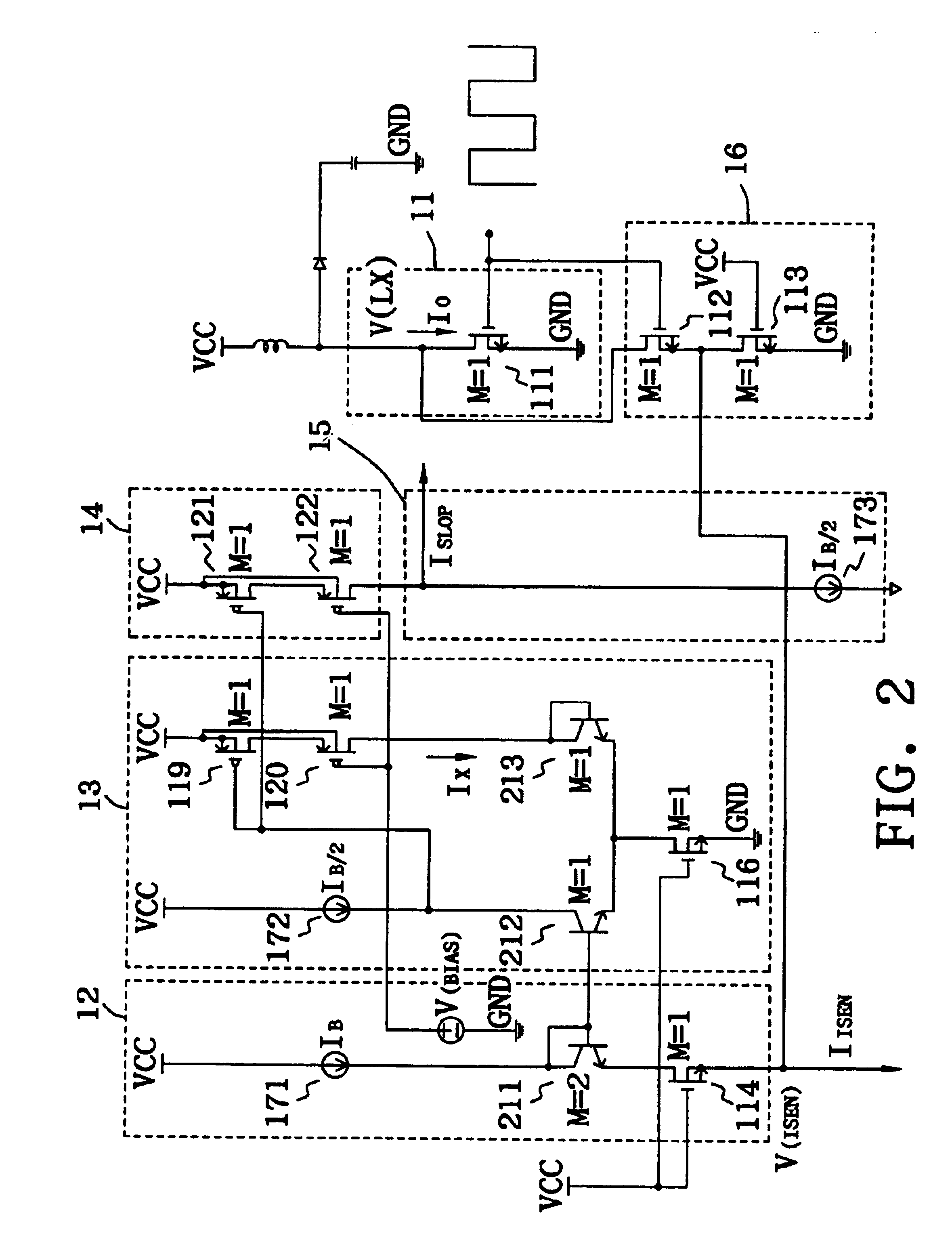
FIG. 1 illustrates a first preferred embodiment of the current sensing circuit of a high-speed driving stage according to the present invention. The current sensing circuit comprises a level converting unit 12, a feedback unit 13, a current mirror unit 14, a current shunting unit 15 and an input stage 16. Generally speaking, in order to reduce power consumption of the output stage transistor 111 of high-speed driving stage 11, the drain to source voltage (V.sub.DS) is usually controlled to be under 0.2 volt, that is, V(LX).ltoreq.0.2 volt. Nevertheless, for the current sensing circuit, it is necessary to further lower the output voltage V(LX) so as to reduce the power consumption. The input stage 16 of the present invention comprises transistors 112 and 113, which can take out the output voltage V(VX) of the high-speed driving stage 11 and divide the voltage for control purposes. The value of the divided voltage V(ISEN) is very small, usually smaller than 0.1 volt and suitable for r...


PUM


Abstract

The present invention discloses a current sensing circuit and method of a high-speed driving stage, which comprises an input stage, a level converting unit, a feedback unit, a current mirror unit and a current shunting unit. The current sensing circuit is capable of linearly detecting the output current of the driving stage transistors, and directly condensing the detected current to an appropriate value using the geometric ratio of the transistors, so as to facilitate the subsequent signal processing circuit to use it for control purposes.

Description

(A) Field of the InventionThe present invention relates to a current sensing circuit and method of a high-speed driving stage, particularly to a current sensing circuit and method of a high-speed driving stage that can largely reduce power consumption.(B) Description of Related ArtTo prevent over-loading in electric circuits with high voltage or current, a current sensing circuit of a driving stage usually needs to be included for detecting abnormal changes in current.A conventional current sensing circuit of a high-speed driving stage requires connecting a current detecting resistance in the driving stage in series, and then using an operational amplifier to enlarge the voltage of the current detecting resistance and convert it into a current for the subsequent signal processing. For this reason, the prior art current sensing circuit has the following drawbacks:1. The use of series resistance will increase power consumption and lower efficiency.2. The use of an operational amplifie...

Claims


Application Information

Patent Timeline
Patent Type & Authority Patents(United States)
IPC IPC(8): H03F3/343H03F3/345H03K17/082H03K17/00G01R19/00H03K5/08H03K5/24
CPCH03F3/345H03K5/2481H03K17/0822H03K5/08G01R19/0092H03K2217/0036
Inventor TZENG, GUANG-NANCHEN, TIEN TZU
Owner GLOBAL MIXED MODE TECH
Why Eureka
Eureka Blog
Learn More