
Multiple access communication system

Inactive Publication Date: 2004-08-17
NEC CORP
View PDF11 Cites 8 Cited by
  • Summary
  • Abstract
  • Description
  • Claims
  • Application Information

AI Technical Summary

Benefits of technology

Further, the user station of the present invention transmits reservation information in bandwidth for random reservation and data packets in bandwidth for random access, by solving collisions on the random reservation system and random access system.
According to the present invention, when traffic on the multiple access channel is light, user stations are able to transmit directly data packets under shorter delay by using random access scheme, rather than using random reservation scheme which suffers unneglectable delay due to reservation and allocation of bandwidth for reserved data packets. Further, according to the present invention, when traffic on the multiple access channel is heavy and collisions occur frequently, the user stations are able to employ random reservation scheme to utilize the multiple access channel efficiently, rather than random access scheme in which loss of bandwidth by collision of data packets is relatively larger than that of reservation packets.

Problems solved by technology

Random reservation scheme achieves good throughput under highly loaded conditions, but has a disadvantage that even under collisionless conditions, packets suffer delay due to reservation process.
But, loss of bandwidth is large, when data packets collide.
Therefore, in highly loaded conditions, the probability of collision rises and the throughput degrades.
Further, in such a multiple-access communication system that the bandwidth for data from user stations are allocated by the key station according to reservation from user stations, the user stations may not be treated fairly, when lengths of data packets are different and bandwidths are allocated in order of reception of reservation by the key station.
However, these algorithms such as the weighted fair queueing increases a load on CPU, when reservations from the user stations come frequently, which is the case in such a system that includes great many user stations.

Method used


Image

  • Multiple access communication system
  • Multiple access communication system
  • Multiple access communication system

Examples


Embodiment Construction

Four modes of embodiment of the present invention are explained, referring to the drawings.

At first, general features common to the four modes of embodiment of the present invention are explained.

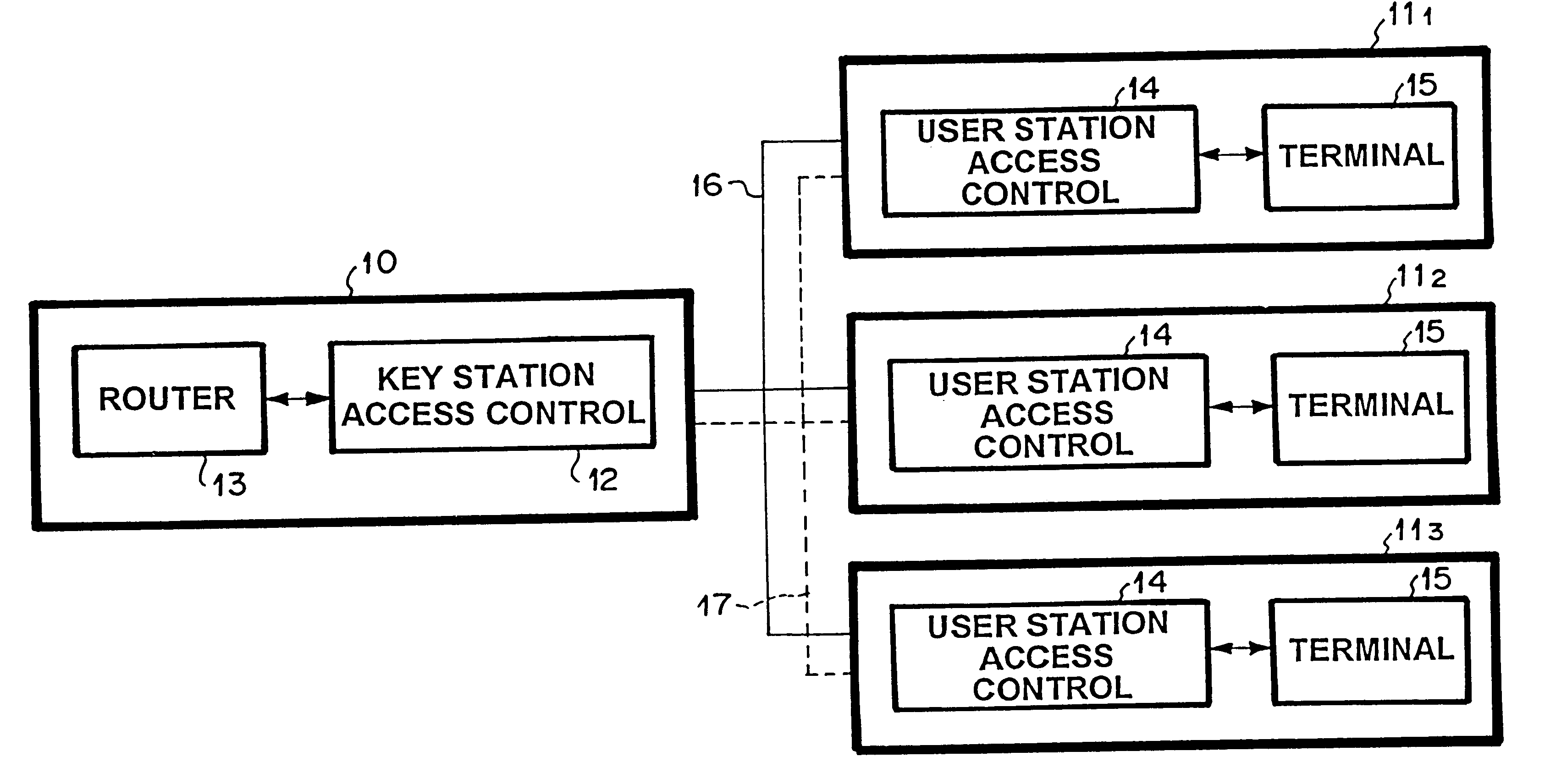
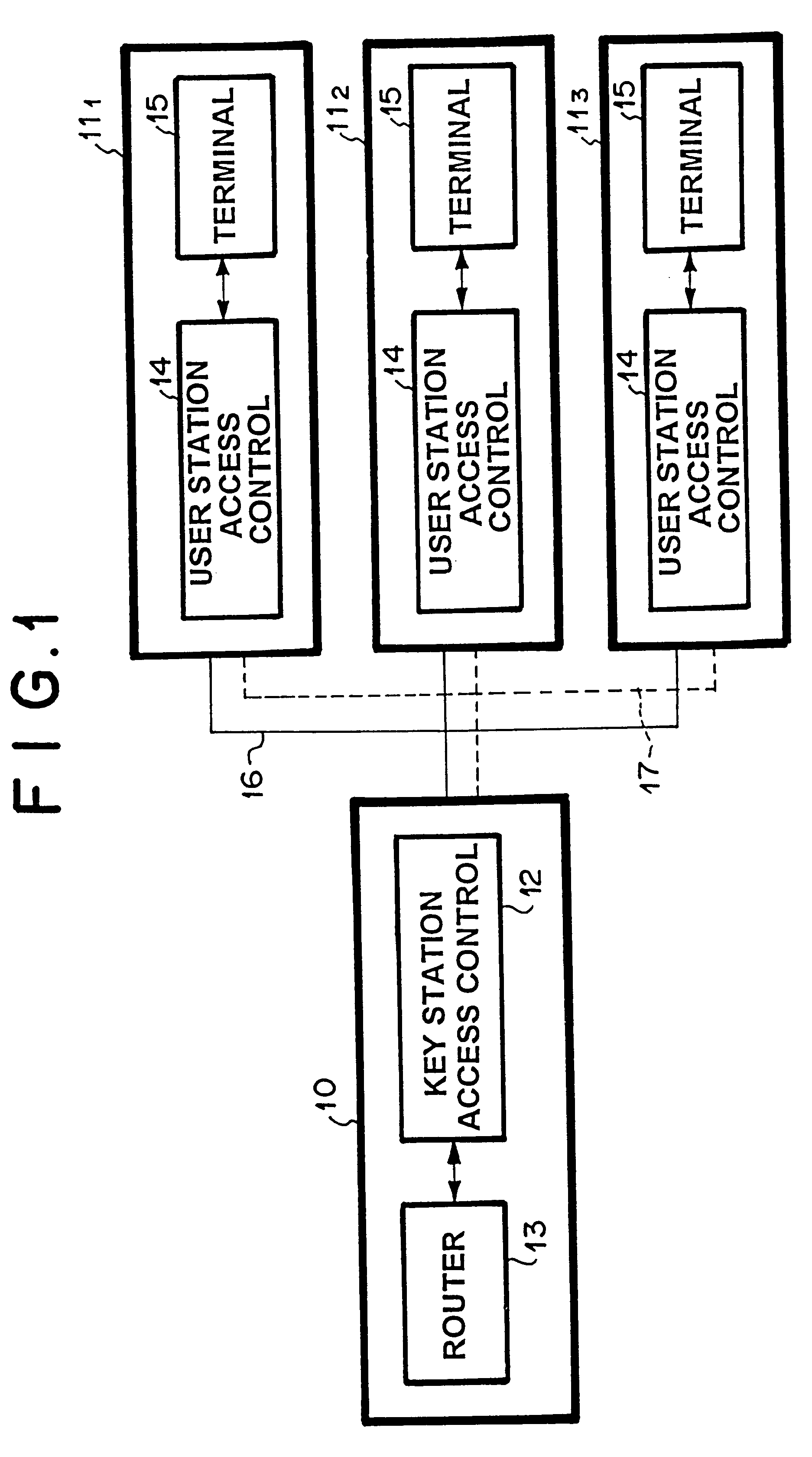
A system comprising key station 10 and user stations 11.sub.1, 11.sub.2 and 11.sub.3 is shown in FIG. 1. Key station 10 comprises key station access control equipment 12 and router 13. Each of user stations 11.sub.1, 11.sub.2 and 11.sub.3 comprises user station access control equipment 14 and terminal 15. The downward data and control signal from key station 10 are transmitted through broadcast type channel 16 to all the user stations, while the upward data from user stations are transmitted through multiple access channel 17. Here, broadcast type channel 16 and multiple access channel 17 may be wired or wireless.

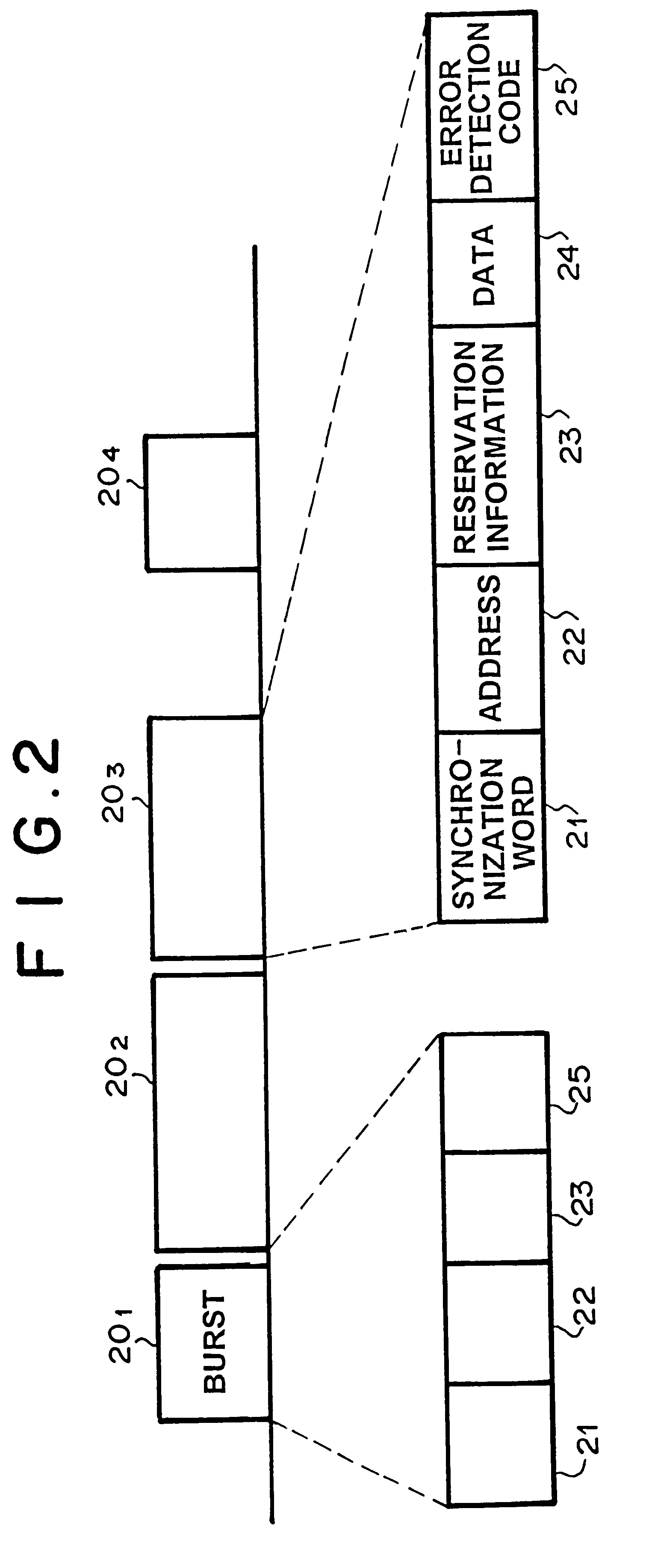
A structure of signal from the user station to the key station in multiple access channel 17 is shown in FIG. 2. Burst signals 20.sub.1, to 20.sub.4 from the user stations are mult...


PUM


Abstract

To achieve high throughput by using random reservation scheme, when traffic is heavy in multiple access communication system. Further, to suppress signal delay by using both random reservation scheme and random access scheme, when the traffic is low. Scheduling means holds a flag which indicates that there is no allocation of transmission bandwidth for a long packet reservation information stored in long packet reservation queue. The flag is checked, after the allocation of data transmission bandwidth is started. When the flags are set, bandwidths are allocated firstly for long packets, and secondly for short packets. On the other hand, when the flag is not set, bandwidths are allocated firstly for short packets, and secondly for long packets.

Description

1. Technical Field of the InventionThe present invention relates to a multiple access communication system such as, but not limited to, a CATV network, or a wide area network (WAN).2. Description of the Prior ArtConventionally, a WAN such as a satellite communication system, or cable modem system holds communication medium in common, and a key station and a plurality of user stations communicate with each other via this medium. Control signals and data signals from the key station are broadcasted on a broadcast type communication channel to all of the user stations, while data signals from user stations to the key station are transmitted on multiple access type channel by time division multiple access (TDMA) scheme. In general, a WAN has several hundreds or several thousands of user stations, but much fewer user stations are transmitting data simultaneously. Therefore, so-called demand-assign-multiple-access scheme which allows only the user stations demanding data transmission to u...

Claims


Application Information

Patent Timeline
IPC IPC(8): H04B7/204H04L29/08H04J3/16H04L12/28
CPCH04B7/204
Inventor UEMATSU, AKIRA
Owner NEC CORP
Learn More