Automotive lighting device

a technology for automotive lighting and lighting devices, applied in lighting and heating apparatus, printing, instruments, etc., can solve the problems of short life expectancy, poor power use efficiency drawbacks of incandescent light bulbs, etc., and achieve the effect of reducing heat flow problems

Inactive Publication Date: 2004-08-10
NORTH AMERICAN LIGHTING
View PDF19 Cites 37 Cited by
  • Summary
  • Abstract
  • Description
  • Claims
  • Application Information

AI Technical Summary

Benefits of technology

The lighting device of embodiments of the present invention may provide an exterior automotive lighting device that has a light source comprising a single LESD. The single LESD preferably complies with photometric requirements of automobile lighting devices. A heat management system is also provided to reduce heat flow problems present within existing automotive lighting devices.

Problems solved by technology

However, incandescent light bulbs have drawbacks.
For example, incandescent light bulbs have poor power use efficiency, and a short lifetime expectancy.
Existing solutions using LED lamps for exterior automotive lighting require a lamp design to accommodate a number of LEDs, further complicated by a heat management solution that is required to dissipate heat generated by the large number of LEDs present within a system.
Such a device has thermal and packaging problems due to the large number of LEDs necessary for the required output and operation of the device.
Existing LED lamps that utilize multiple LED light sources to fulfill light output requirements are difficult to manufacture due to a complexity of a light fixture design.

Method used


Image

  • Automotive lighting device
  • Automotive lighting device
  • Automotive lighting device

Examples


Embodiment Construction

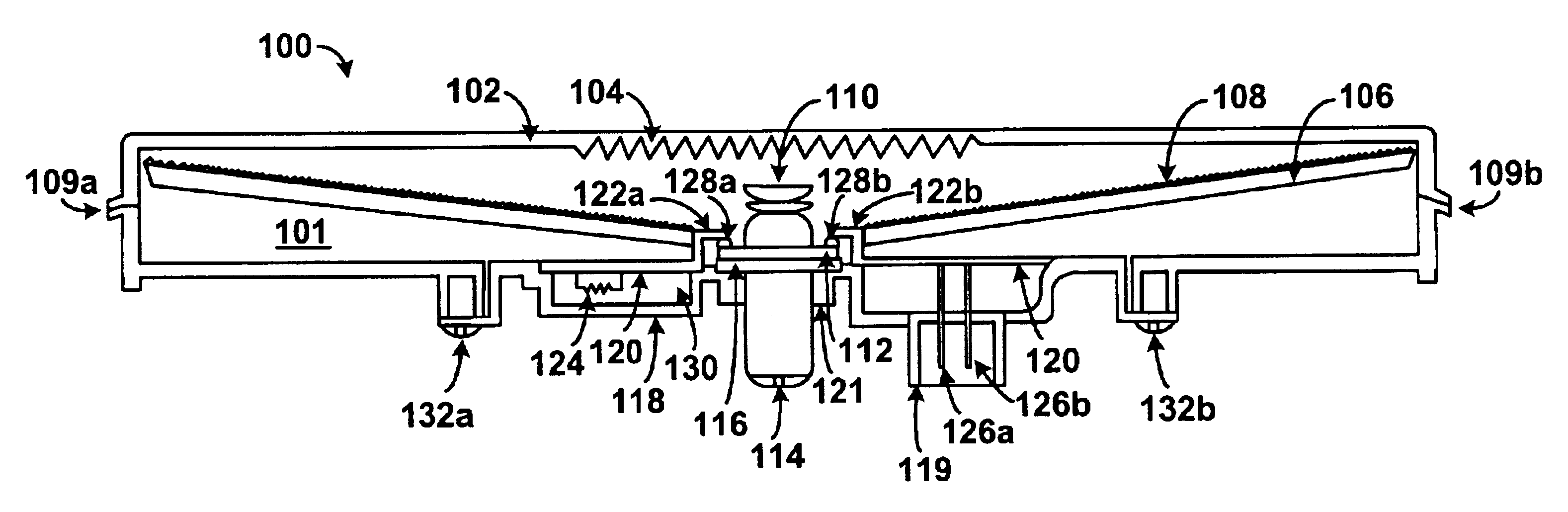
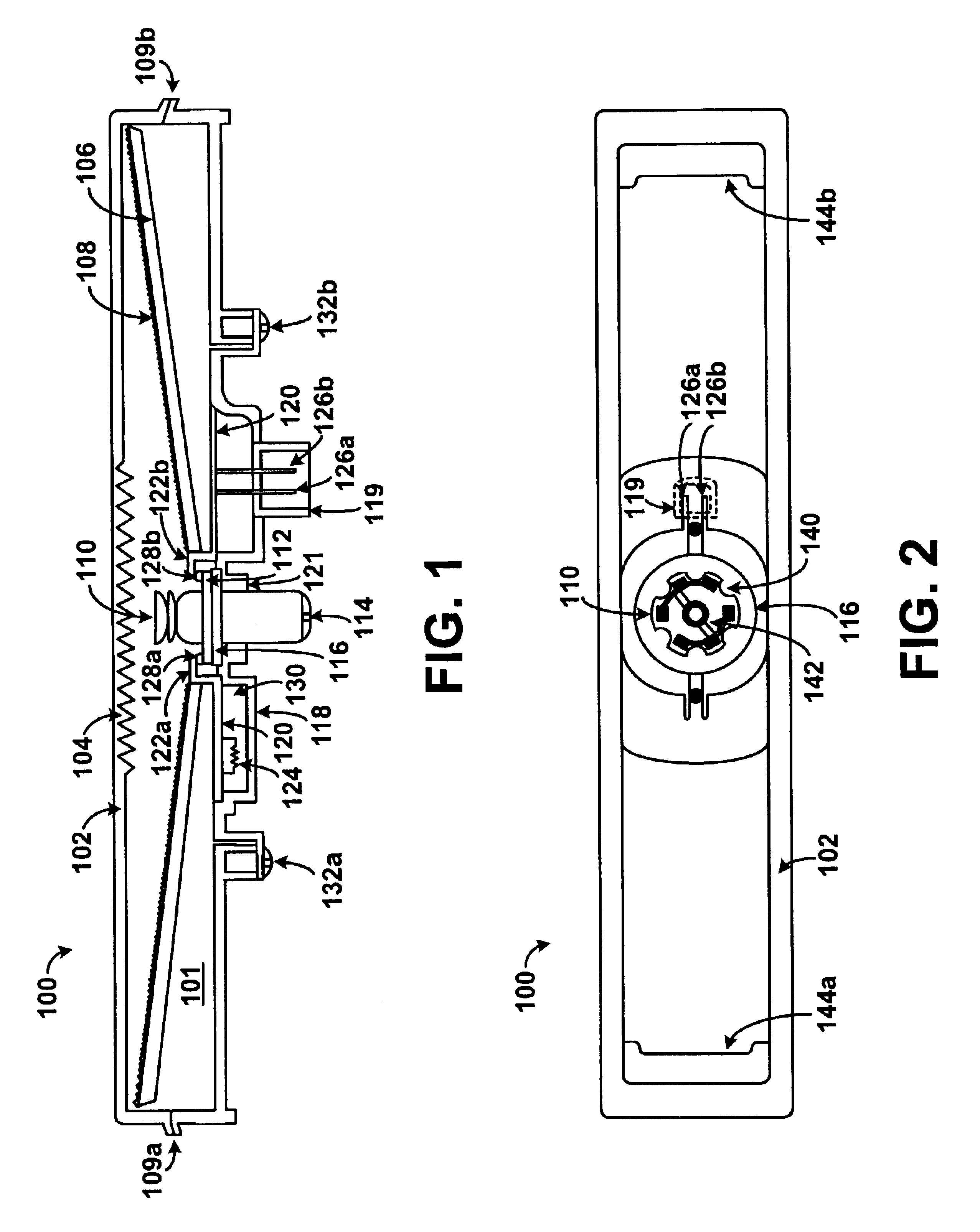
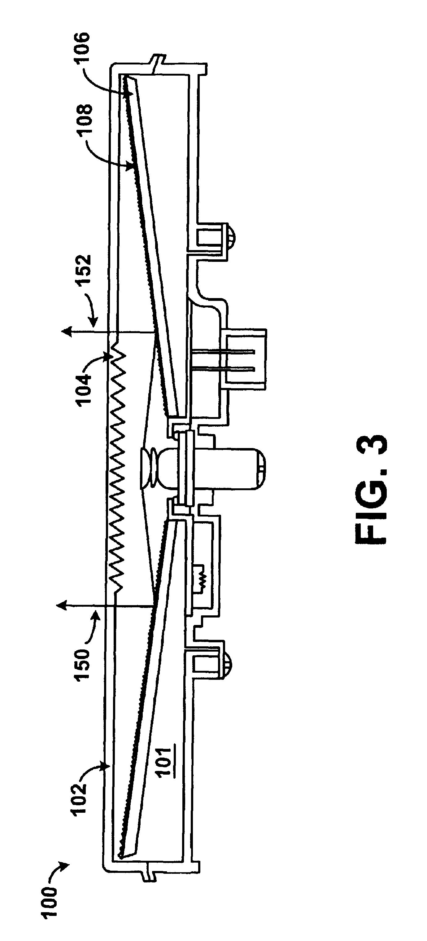
FIG. 1 illustrates a side view of one embodiment of an exterior automobile lighting device. It should be understood that the lighting device illustrated in FIG. 1 and other arrangements described herein are set forth for purposes of example only, and other arrangements and elements can be used instead and some elements may be omitted altogether, depending on manufacturing and / or consumer preferences.

By way of example, FIG. 1 illustrates a high mount stop lamp 100. The high mount stop lamp 100 comprises a light guide 101 which has a lens 102 and a reflector 106. The lens has retroactive optics 104 on an inner surface to direct light in multiple directions, and to hide a view of components of the light guide 101. The retroactive optics 104 receive radiated light and distribute the light in a plurality of directions. The light guide 101 may also include an outer lens (not shown) coupled to the light guide 101 to receive radiated light from the lens 102 and to further reflect the radiat...


PUM


Abstract

An exterior automotive lighting device is provided. The device includes a light guide housing and a single Light Emitting Semiconductor Device (LESD). The light guide housing includes reflective material and optical elements to reflect emitted photons from the single LESD in multiple directions. The light guide has a thermally conductive material and thermally conductive connectors to dissipate heat generated by the single LESD. The lighting device may be used in accordance with lighting systems, such as a high mount stop lamp and a tail lamp on an automobile.

Description

The present invention relates to automotive lighting devices, and more particularly, to employing a single Light Emitting Semiconductor Device (LESD) in lighting devices for exterior automotive lighting applications.BACKGROUND OF INVENTIONExterior automotive lighting, such as tail lights and brake lights, has typically been accomplished using incandescent light bulbs mounted in specifically designed lighting fixtures. Incandescent light bulbs provide a necessary light intensity required by law for use in automotive lighting applications. However, incandescent light bulbs have drawbacks. For example, incandescent light bulbs have poor power use efficiency, and a short lifetime expectancy. As an alternative to incandescent light bulbs, Light Emitting Diode (LED) lamps have also been used in tail lights and brake lights in vehicles such as, cars, motorcycles, forklifts, ATVs, trailers, and other motor vehicles. LEDs can be designed to maximize brightness and fill an entire area of a li...

Claims


Application Information

Patent Timeline
Patent Type & Authority Patents(United States)
IPC IPC(8): B60Q1/26F21V29/00F21S8/12F21S8/10F21K99/00
CPCB60Q1/26F21K9/00F21S48/215F21V29/83F21S48/328F21V29/004F21V29/74F21S48/1241Y10S362/80F21S48/2225F21S41/24F21S43/14F21S43/235F21S45/47F21S45/48F21V29/85
Inventor DESAI, DEVAL M.
Owner NORTH AMERICAN LIGHTING
Why Eureka
Try Eureka