Minimizing standby power in a digital addressable lighting interface

Inactive Publication Date: 2004-07-13
MICROCHIP TECH INC
View PDF3 Cites 52 Cited by
  • Summary
  • Abstract
  • Description
  • Claims
  • Application Information

AI Technical Summary

Problems solved by technology

However, the DALI hardware interface requires a power source for monitoring address and control information on the DALI bus even when the associated ballast and power controller are off.
A separate power supply for each DALI hardware interface requires space and may amount to a significant percentage of the cost of the DALI hardware interface.
Also, having to continuously supply power to each DALI hardware interface amounts to a significant amount of power in a building having hundreds of light figures.

Method used


Image

  • Minimizing standby power in a digital addressable lighting interface
  • Minimizing standby power in a digital addressable lighting interface
  • Minimizing standby power in a digital addressable lighting interface

Examples


Embodiment Construction

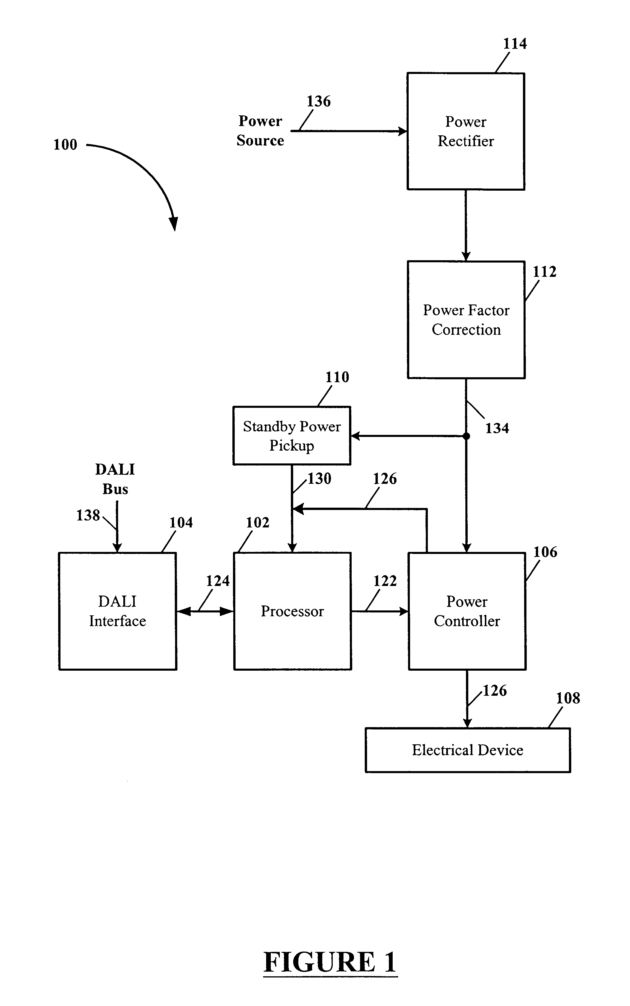
The present invention is directed to a method, system and apparatus for minimizing standby power in a digital addressable lighting interface (hereinafter "DALI") when an associated DALI compliant device is off or inactive. Exemplary embodiments of the present invention include a DALI having a standby mode and an active mode. When in the active mode, power is supplied to the DALI by an associated power controller, and when in the standby mode, power may be supplied to the DALI by a high resistance voltage dropping resistor connected to a high voltage DC source rectified from the AC line voltage power source. The power source may also be direct current (DC) in which case no rectification would be necessary. The standby power for the DALI may also be supplied by either a low power step down transformer or a high impedance voltage dropping element, e.g., a capacitor or an inductor, connected to the AC line voltage power source in combination with a rectifying diode. The DALI uses less c...


PUM


Abstract

A Digital Addressable Lighting Interface (DALI) receives power from a high voltage power circuit when in a standby mode. The DALI remains in a standby mode until signal activity on a DALI bus is detected, or the DALI may periodically switch from the standby mode to an active mode so as to sample any activity on the DALI bus. If no activity is detected then the DALI returns to the standby mode. If DALI bus activity is detected then the DALI remains in the active mode. The DALI receives power from a power controller when in the active mode. The DALI remains in the active mode so long as the power controller is supplying power to an electrical device.

Description

The present invention relates generally to control and status of building lighting and power systems, and more particularly to a minimizing standby power in a digital addressable lighting interface (DALI).BACKGROUND OF THE INVENTION TECHNOLOGYThe demands imposed on lighting systems have changed considerably in recent years. Heretofore, switching individual or groups of luminaries on and off used to be sufficient, however, the focus for today and in the future will be on dynamic lighting. Energy conservation, more flexibility of use, increased life and reduced maintenance costs of lighting systems require lighting scene control. To create lighting scenes, luminaries generally are assigned to a plurality of groups. In addition, an end user preferably wants the option of controlling his or her luminaries. If installations having this type of flexibility are integrated into a building management system, there is also a need for simple check-back of operational status as well as global o...

Claims


Application Information

Patent Timeline
IPC IPC(8): H05B37/02H02J9/00
CPCH05B37/0254H02J9/005H05B47/18Y02B70/30Y04S20/20
Inventor FOSLER, ROSS M.
Owner MICROCHIP TECH INC
Why Eureka
Try Eureka